GM Service Manual Online
For 1990-2009 cars only
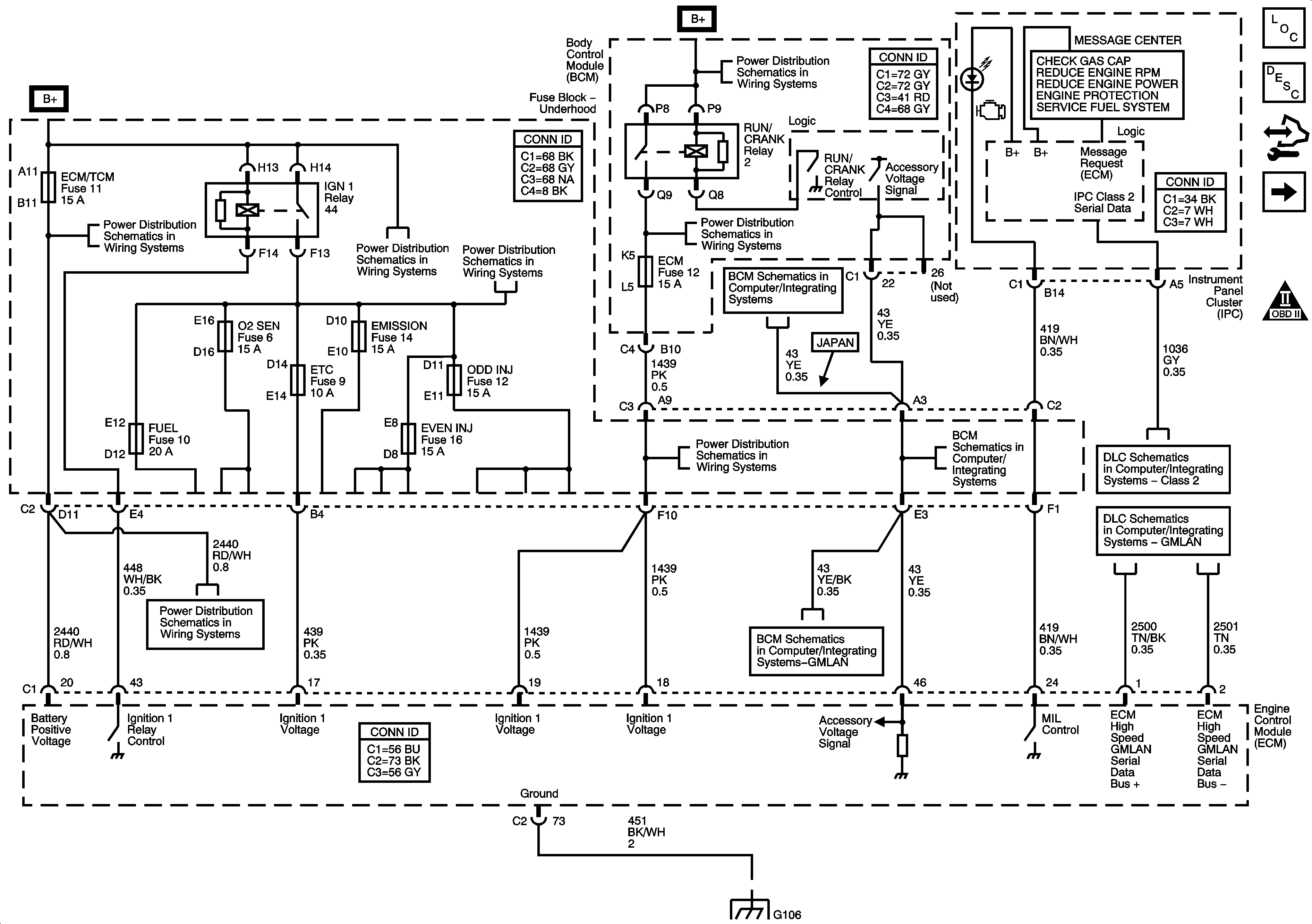
Figure 1:

DLC, Ground, MIL, and Power


Object Number: 1480622  Size: FS
Master Electrical Component List
Engine Control Module Description
Control Module References
12-Volt and 5-Volt Reference Bussing
Engine Controls Schematic Icons
Fuse Block Underhood Fuses: ABS, AMP, BATT2, COOLFAN, ECM/TCM, HORN, HVAC, MRRTD, W/S WASH
Fuse Block Underhood Fuses: EMISSION, ETC, EVEN INJ, FUEL, O2SEN, and ODD INJ
BCM Fuses: ECM, GMLAN Devices, RPA/H/C SEAT and SDM/PSIR SW, Fuse Block Underhood Fuses - ABS/MRRTD, and ACC/TCM
06 XLR Body Control System Schematics - DLC, Power, and Ground
BCM Fuses: ECM, GMLAN Devices, RPA/H/C SEAT and SDM/PSIR SW, Fuse Block Underhood Fuses - ABS/MRRTD, and ACC/TCM
06 XLR Body Control System Schematics - DLC, Power, and Ground
Class 2
GM LAN
Fuse Block Underhood Fuses: ABS, AMP, BATT2, COOLFAN, ECM/TCM, HORN, HVAC, MRRTD, W/S WASH
06 XLR Body Control System Schematics - DLC, Power, and Ground
G104 and G106
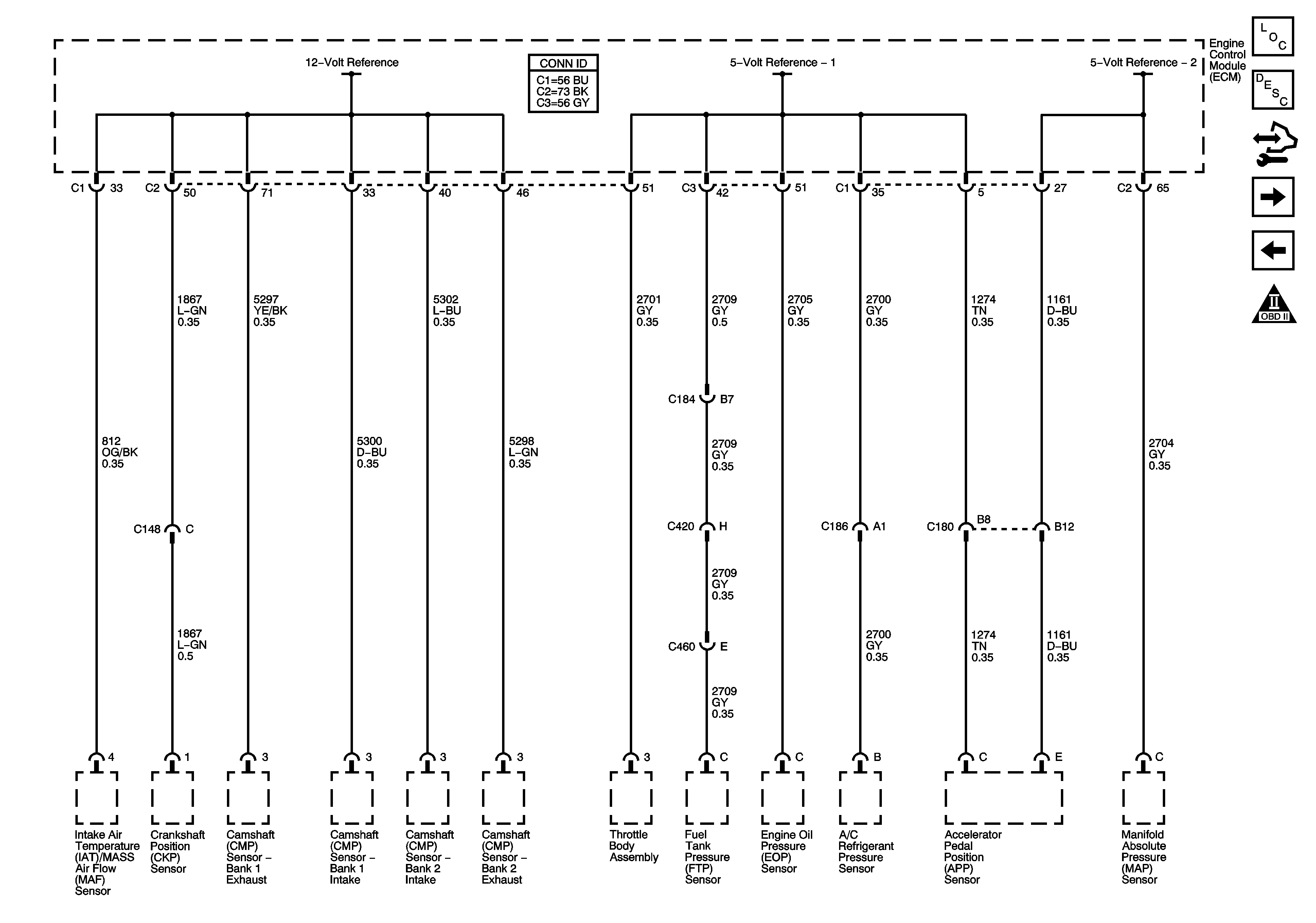
Figure 2:

12-Volt and 5-Volt Reference Bussing


Object Number: 1480624  Size: FS
Master Electrical Component List
Engine Control Module Description
Control Module References
Low Reference Bussing
DLC, Ground, MIL, and Power
Engine Controls Schematic Icons
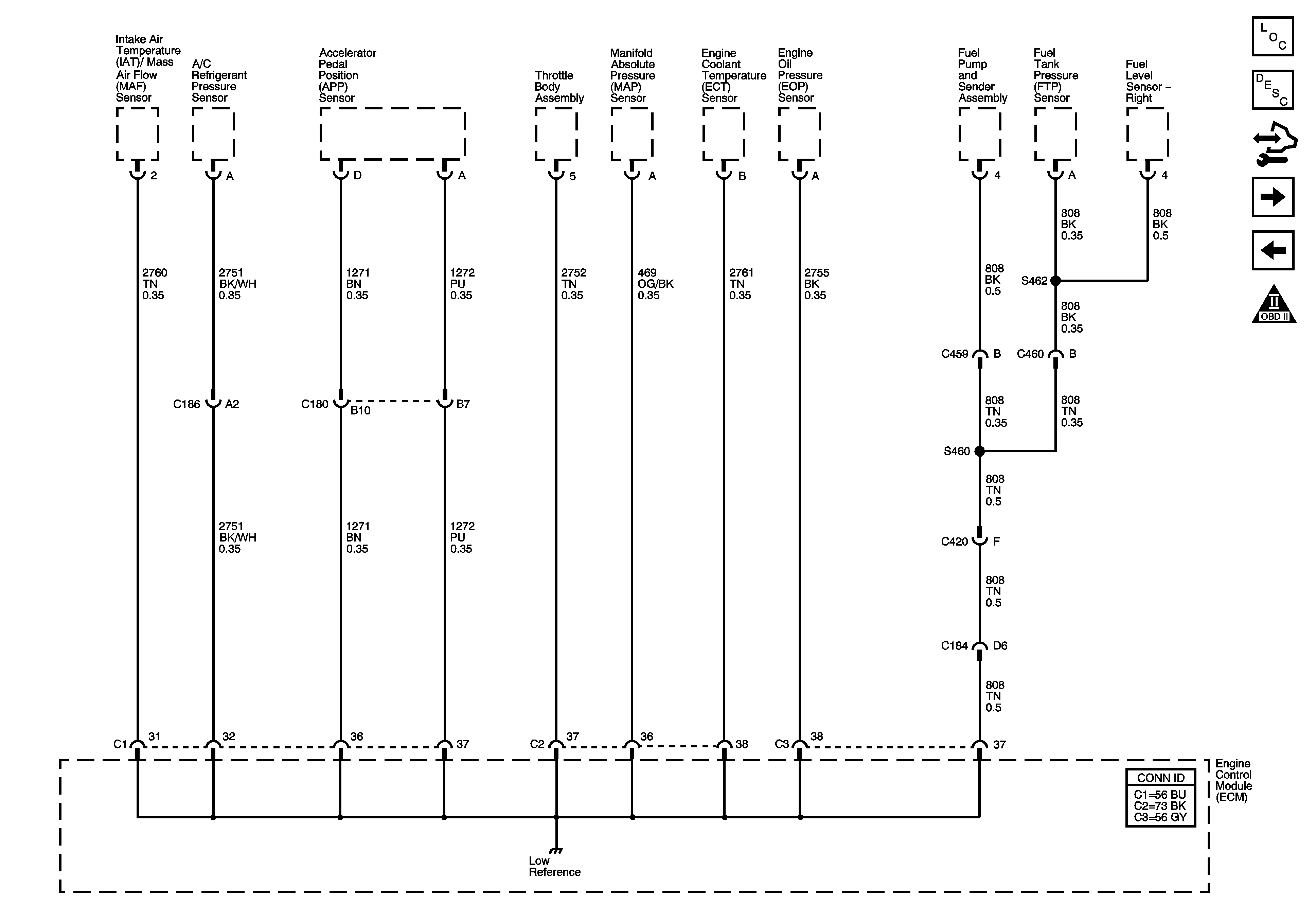
Figure 3:

Low Reference Bussing


Object Number: 1480627  Size: FS
Master Electrical Component List
Engine Control Module Description
Control Module References
Engine Data Sensors - Pressure Temperature, MAF, VSS and Brake Travel
12-Volt and 5-Volt Reference Bussing
Engine Controls Schematic Icons
Figure 4:

Engine Data Sensors - Pressure, Temperature, MAF, VSS, and Brake Travel
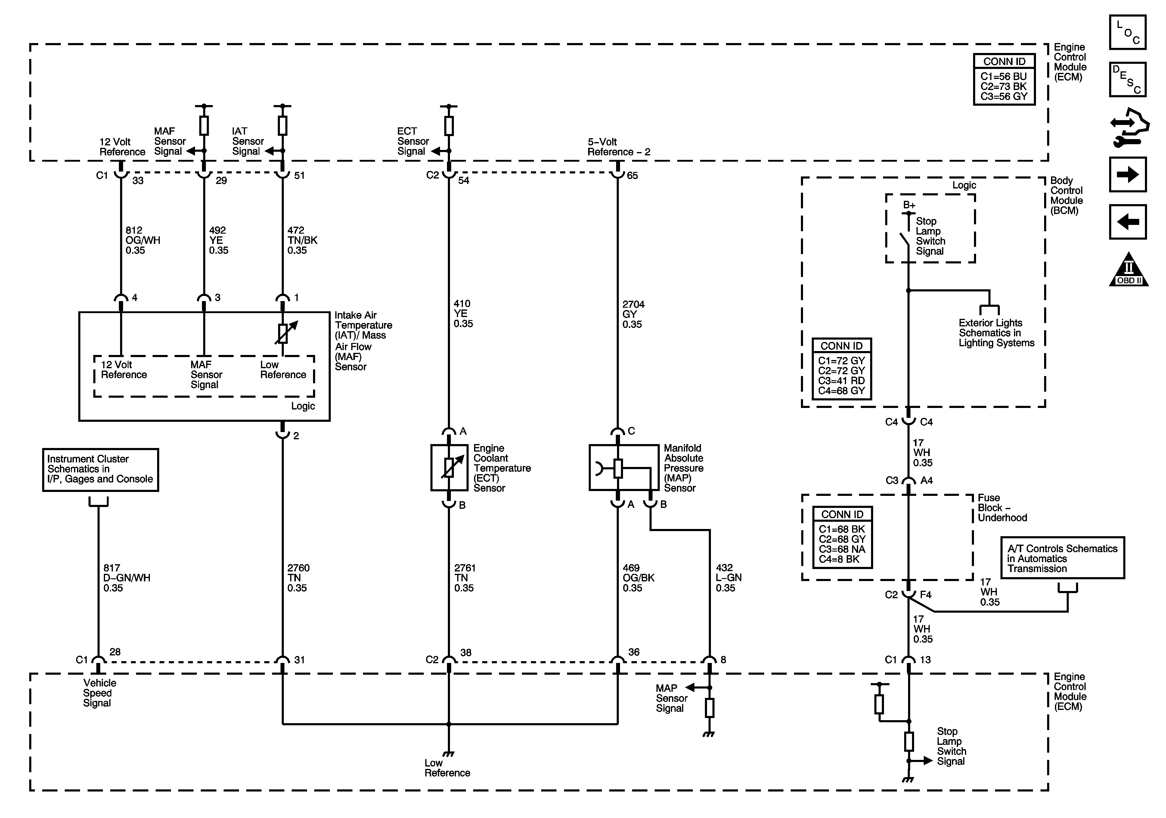

Object Number: 1480629  Size: FS
Master Electrical Component List
Engine Control Module Description
Control Module References
Engine Data Sensors - Oxygen Sensors
Low Reference Bussing
Engine Controls Schematic Icons
Gages
Stop Lamps
Shift Lever
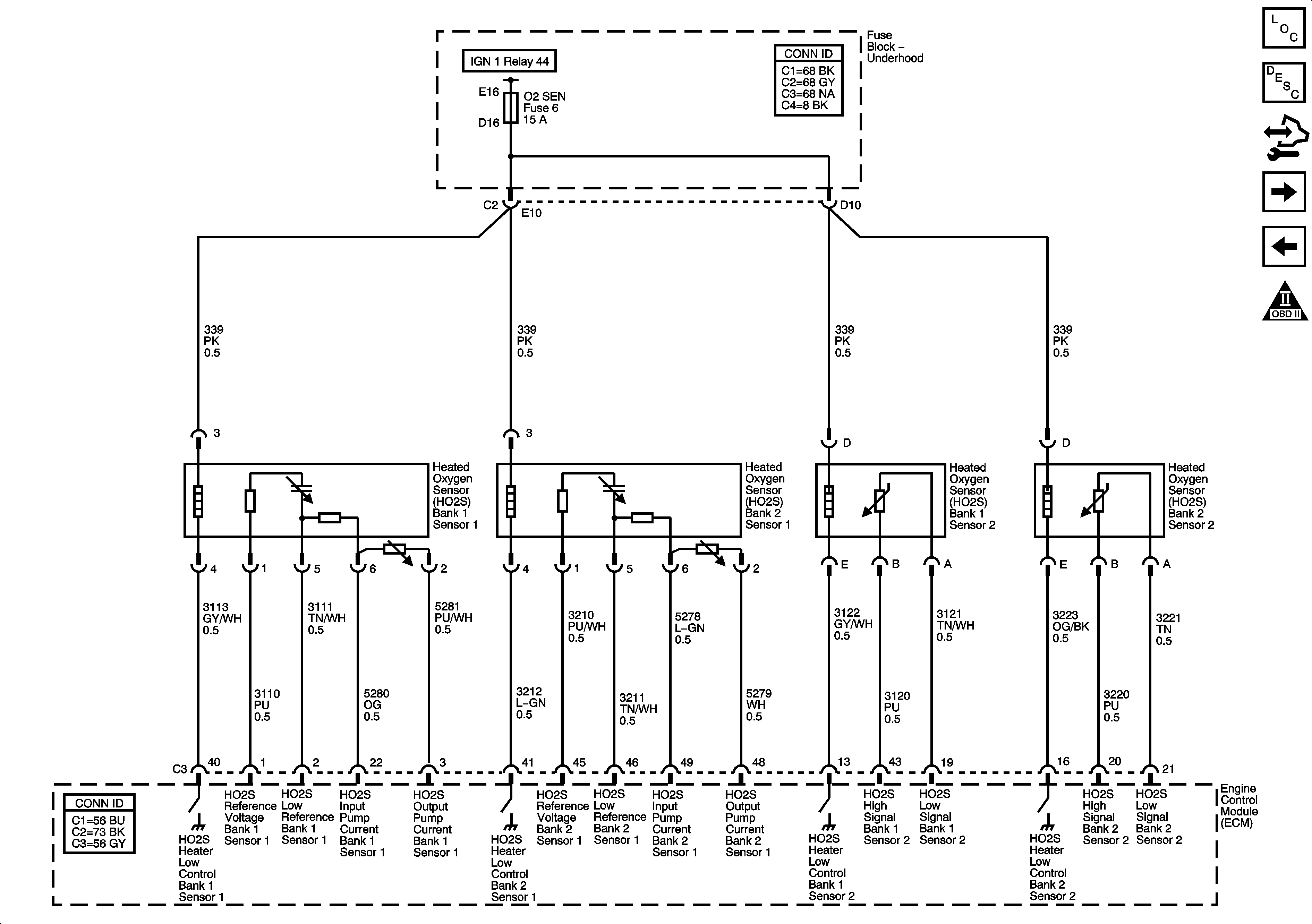
Figure 5:

Engine Data Sensors - Oxygen Sensors


Object Number: 1480633  Size: FS
Master Electrical Component List
Engine Control Module Description
Control Module References
Engine Data Sensors - Electronic Throttle Controls
DLC, Ground, MIL, and Power
Engine Controls Schematic Icons
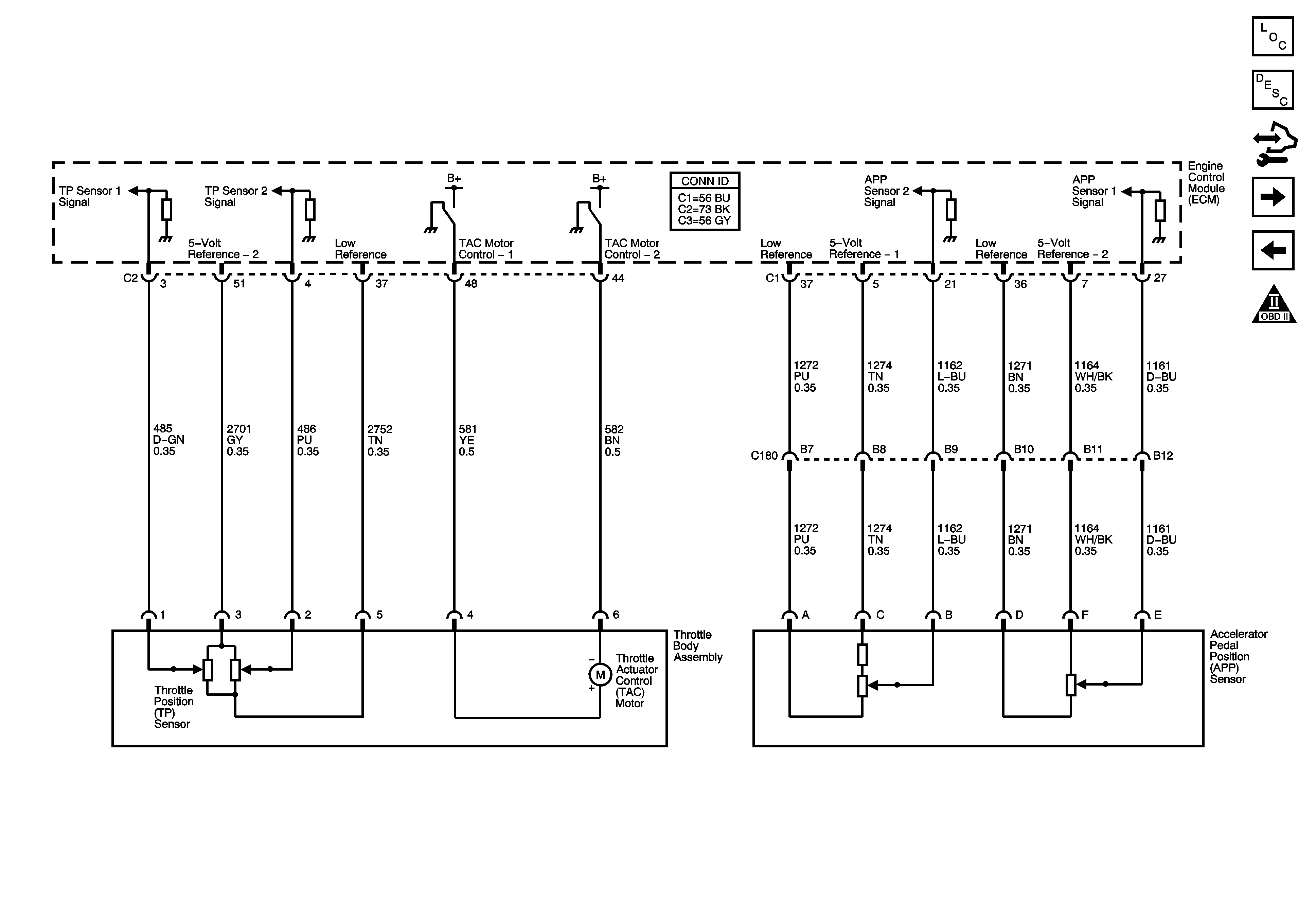
Figure 6:

Engine Data Sensors - Electronic Throttle Controls


Object Number: 1480635  Size: FS
Master Electrical Component List
Engine Control Module Description
Control Module References
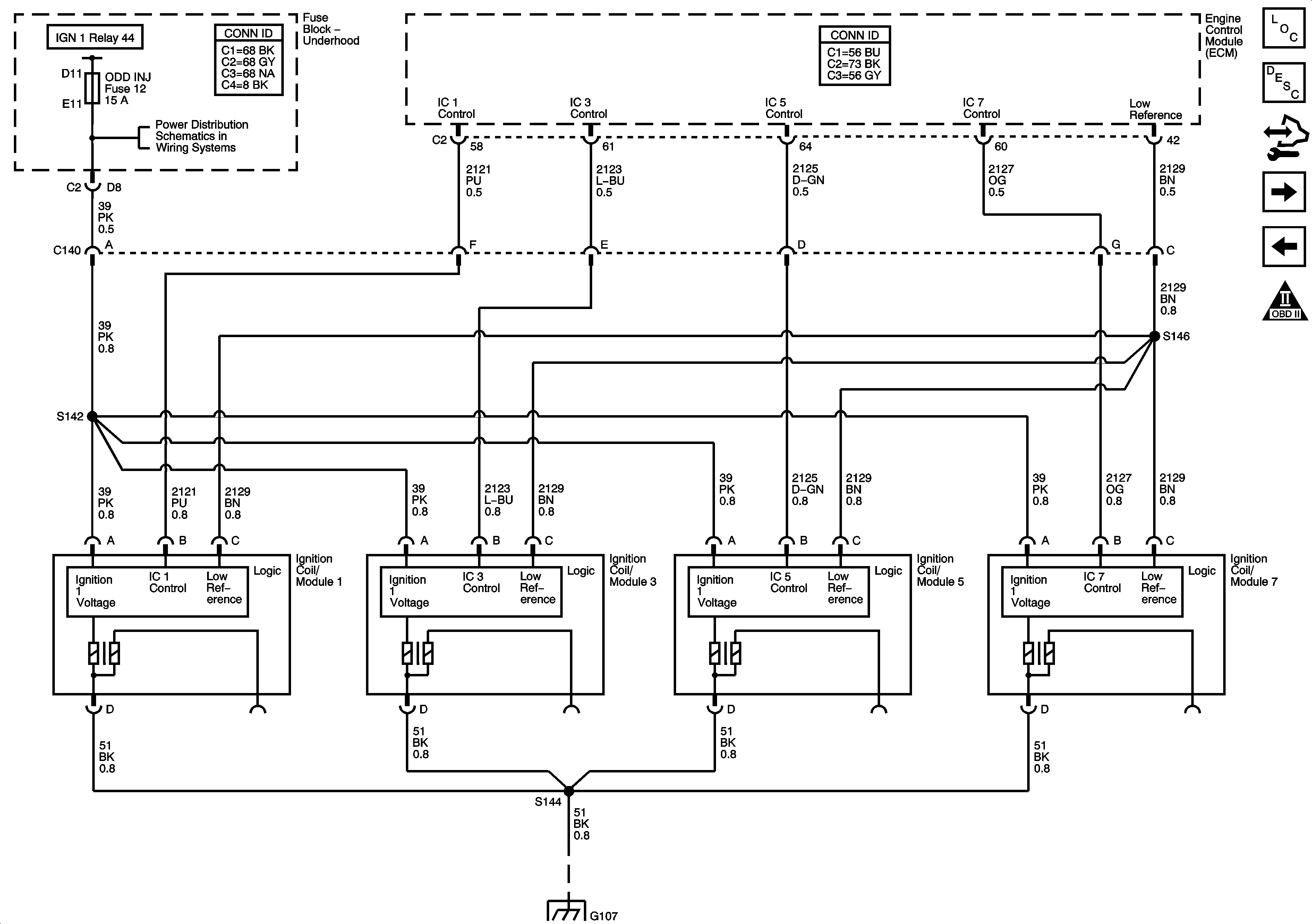
Ignition System - Bank 1
Engine Data Sensors - Oxygen Sensors
Engine Controls Schematic Icons
Figure 7:

Ignition System - Bank 1


Object Number: 1480638  Size: FS
Master Electrical Component List
Engine Control Module Description
Control Module References
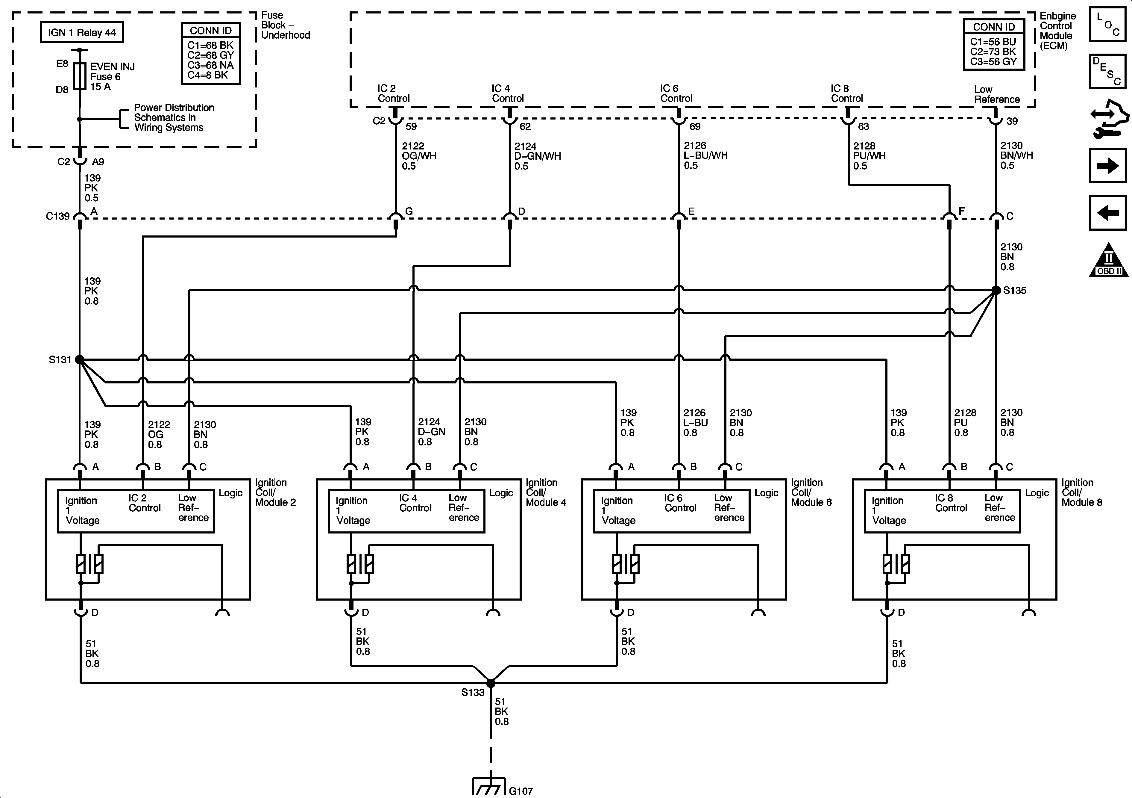
Ignition System - Bank 2
Engine Data Sensors - Electronic Throttle Controls
Engine Controls Schematic Icons
Fuse Block Underhood Fuses: EMISSION, ETC, EVEN INJ, FUEL, O2SEN, and ODD INJ
G105 and G107
Figure 8:

Ignition System - Bank 2


Object Number: 1480641  Size: FS
Master Electrical Component List
Engine Control Module Description
Control Module References
Ignition Controls - CKP and KS Sensors
Ignition System - Bank 1
Engine Controls Schematic Icons
Fuse Block Underhood Fuses: EMISSION, ETC, EVEN INJ, FUEL, O2SEN, and ODD INJ
G105 and G107
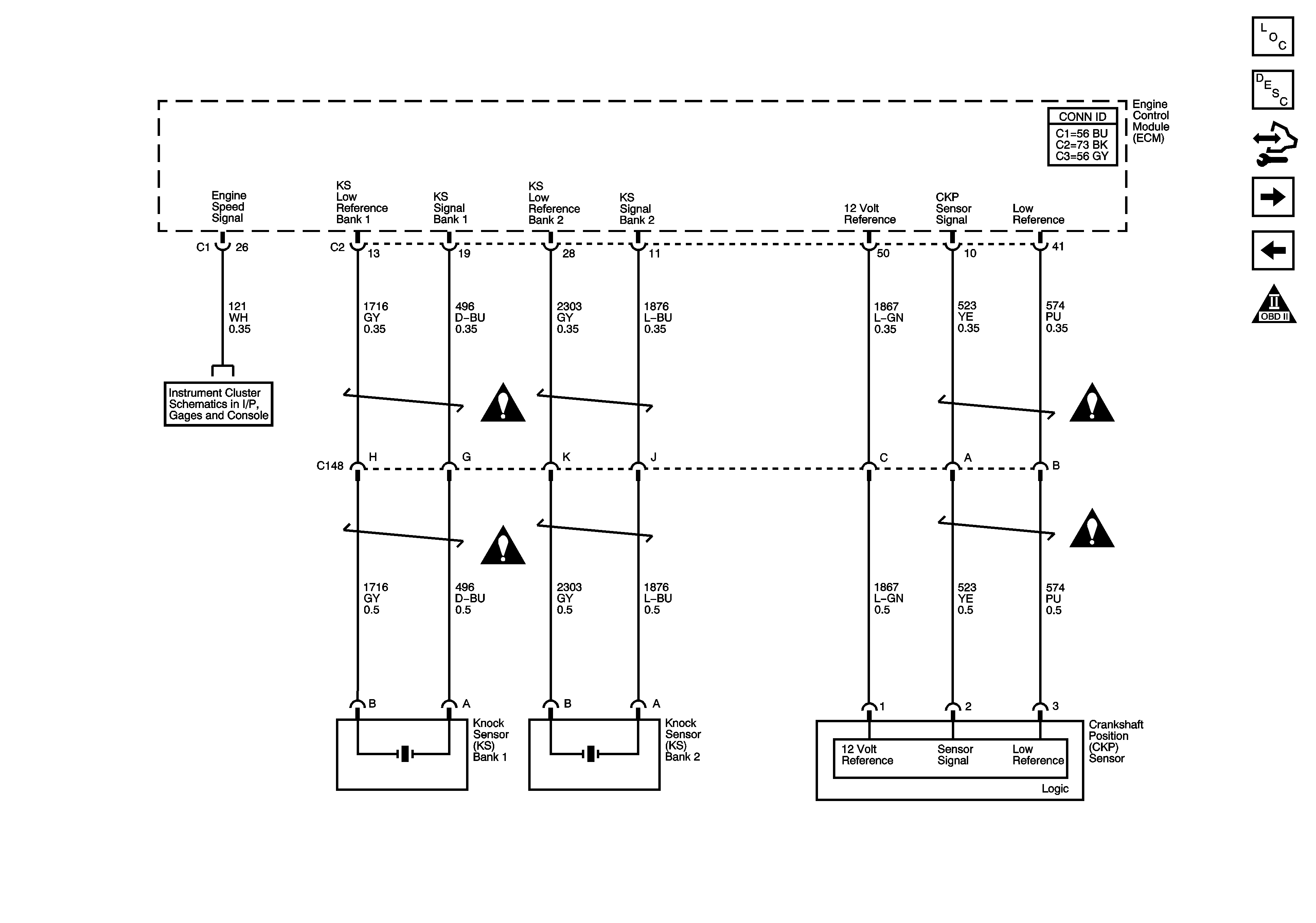
Figure 9:

Ignition Controls - CKP and KS Sensors


Object Number: 1480642  Size: FS
Master Electrical Component List
Engine Control Module Description
Control Module References
Ignition Controls - CMP Sensors and Controls
Ignition System - Bank 2
Engine Controls Schematic Icons
Gages
Engine Controls Schematic Icons
Figure 10:

Ignition Controls - CMP Sensors and Solenoids
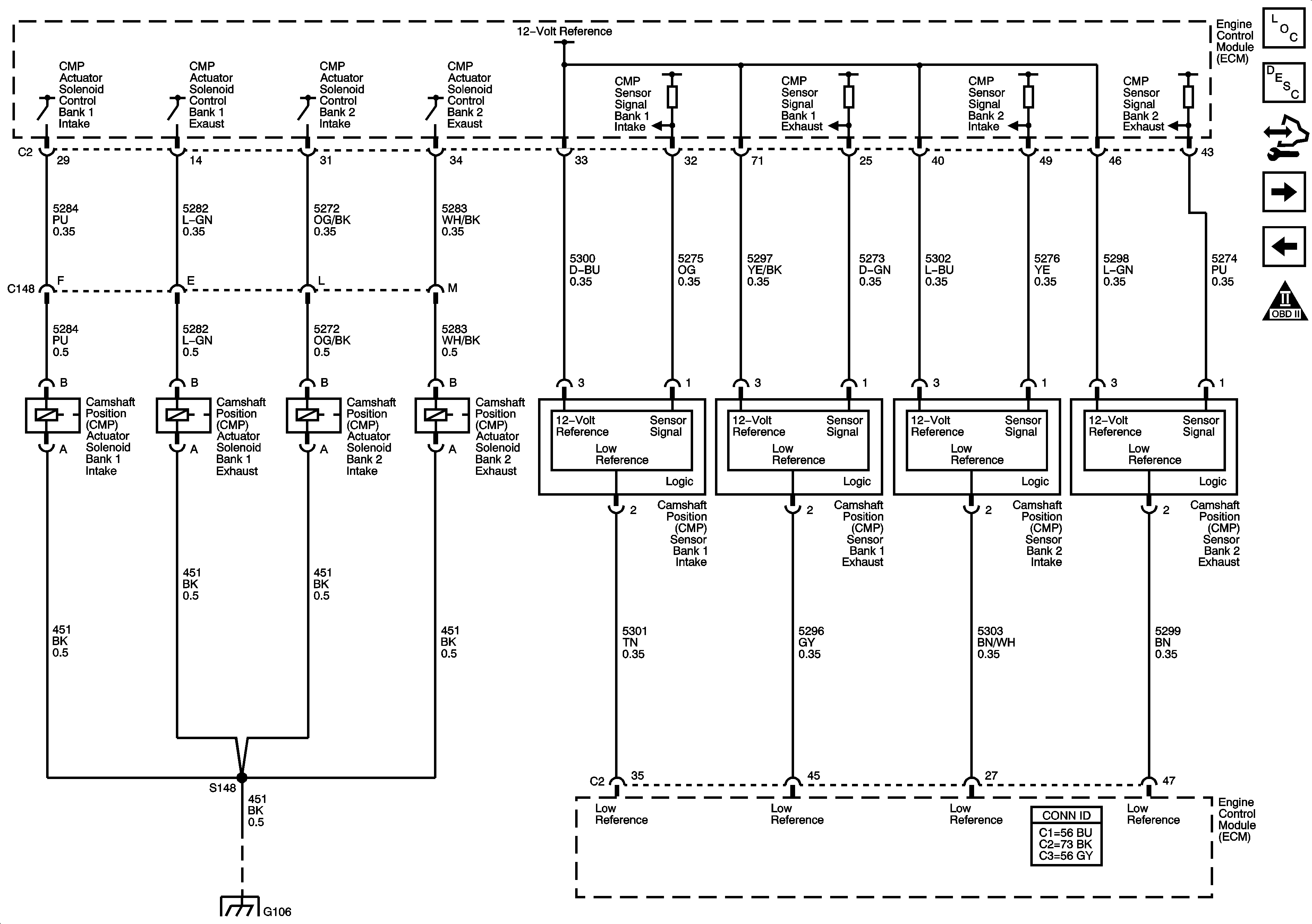

Object Number: 1480644  Size: FS
Master Electrical Component List
Engine Control Module Description
Control Module References
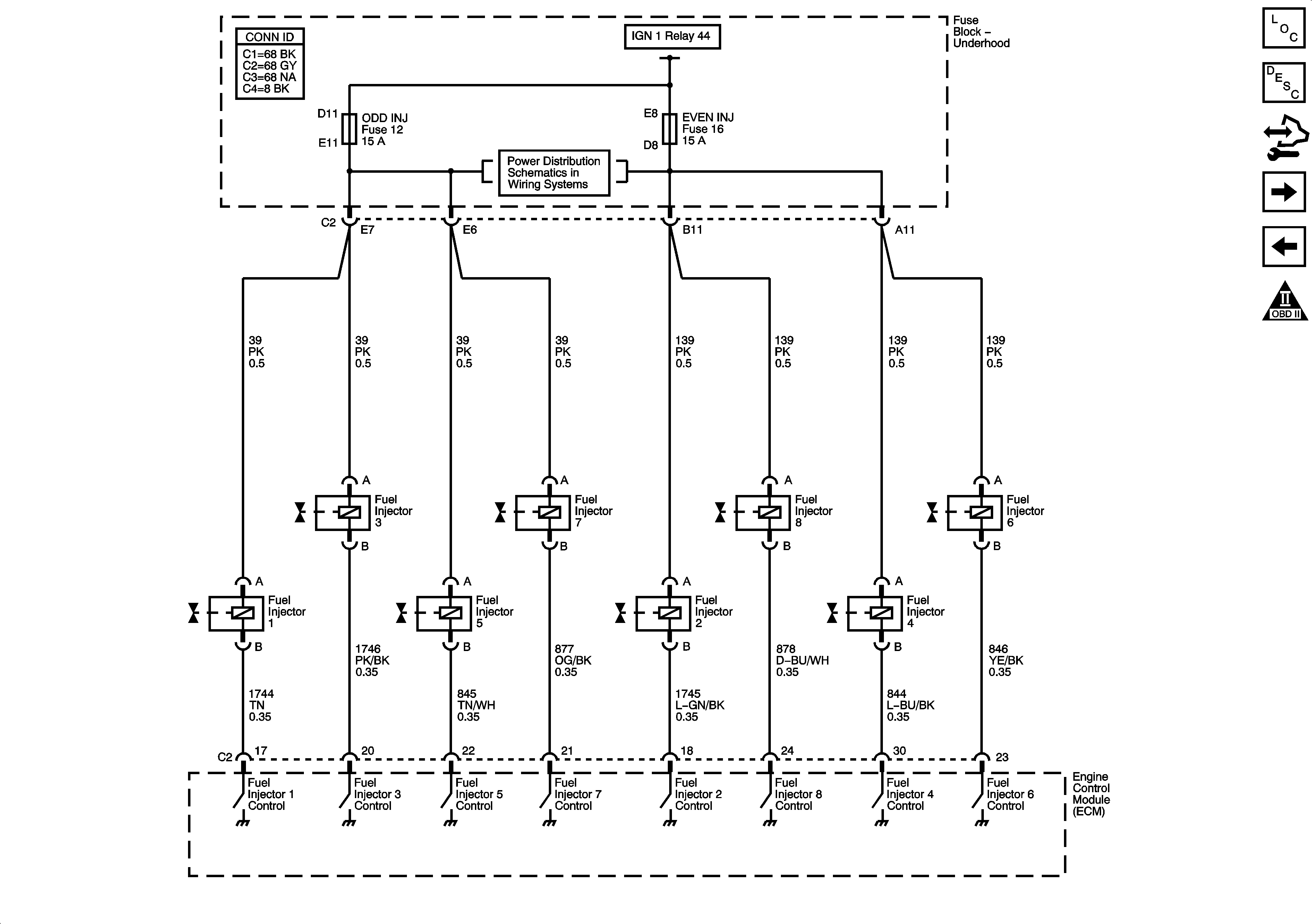
Fuel Controls - Fuel Injectors and Fuel Pump Controls
Ignition Controls - CKP and KS Sensors
Engine Controls Schematic Icons
G104 and G106
Figure 11:

Fuel Controls - Fuel Injectors and Fuel Pump Controls


Object Number: 1676497  Size: FS
Master Electrical Component List
Engine Control Module Description
Control Module References
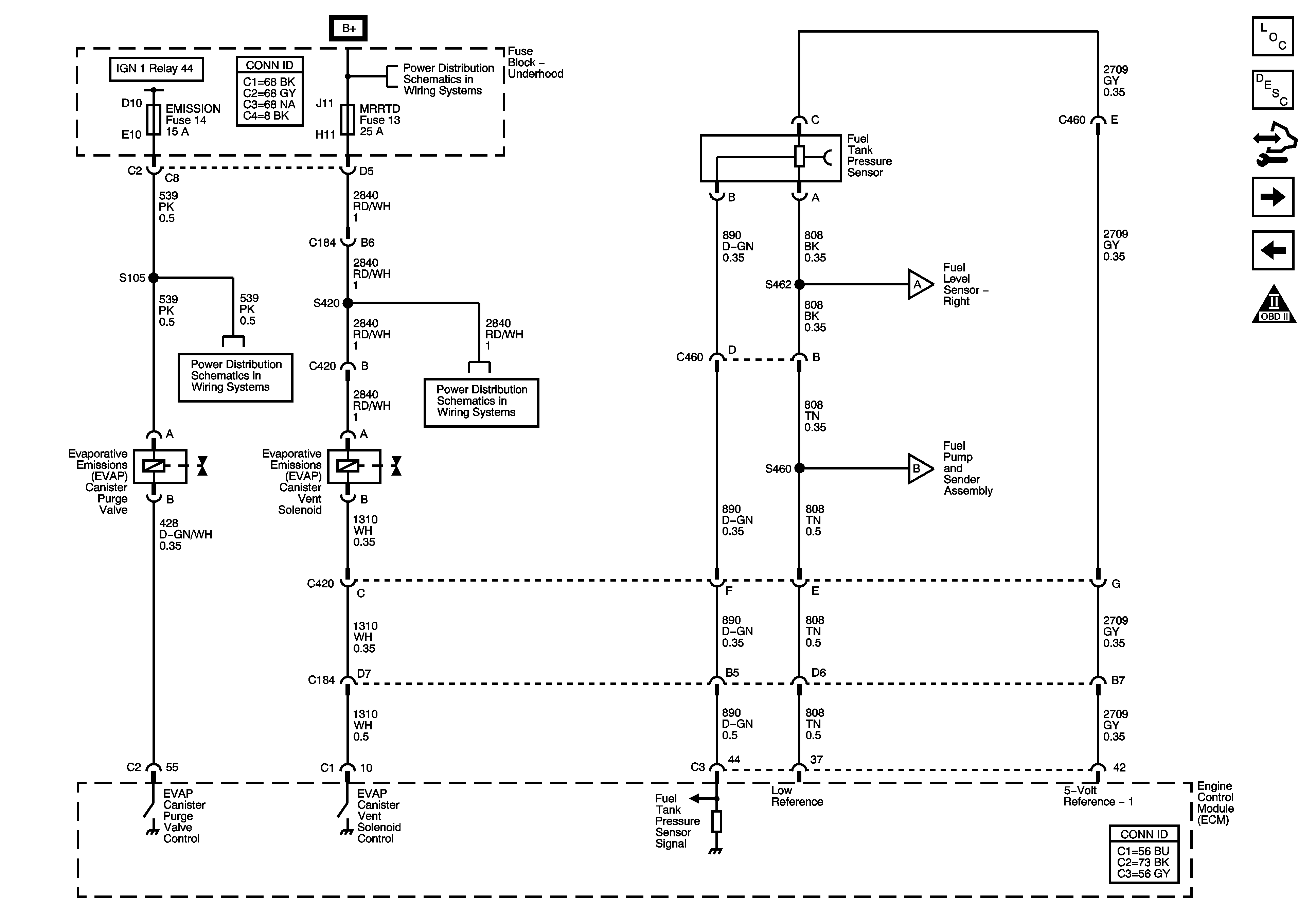
Fuel Controls - EVAP Controls
Ignition Controls - CMP Sensors and Controls
Engine Controls Schematic Icons
Fuse Block Underhood Fuses: EMISSION, ETC, EVEN INJ, FUEL, O2SEN, and ODD INJ
Figure 12:

Fuel Controls - EVAP Controls


Object Number: 1676493  Size: FS
Master Electrical Component List
Engine Control Module Description
Control Module References
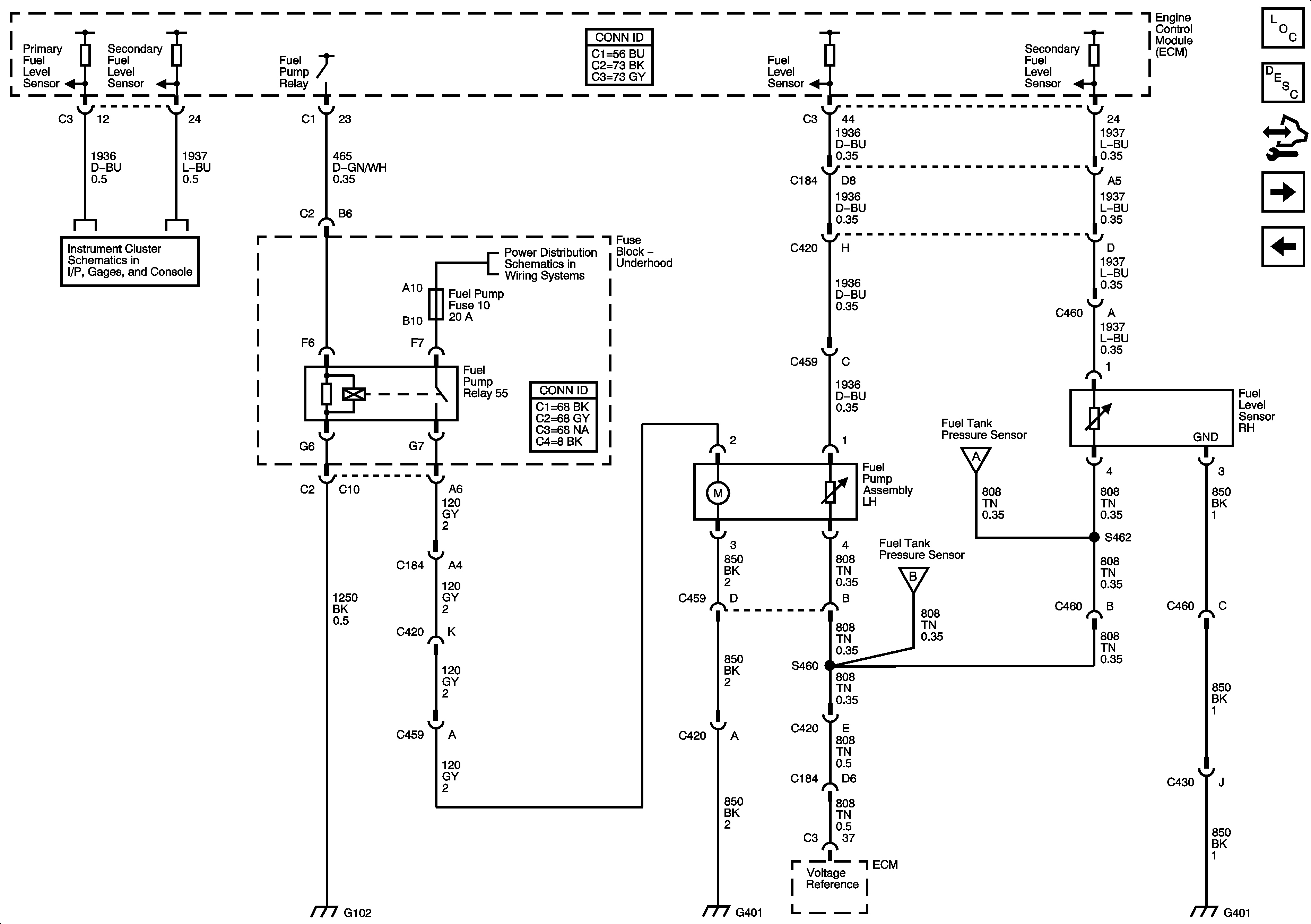
Fuel Pump Controls
Fuel Controls - Fuel Injectors and Fuel Pump Controls
Engine Controls Schematic Icons
Fuse Block Underhood Fuses: ABS, AMP, BATT2, COOLFAN, ECM/TCM, HORN, HVAC, MRRTD, W/S WASH
Fuse Block Underhood Fuses: EMISSION, ETC, EVEN INJ, FUEL, O2SEN, and ODD INJ
Fuse Block Underhood Fuses: ABS, AMP, BATT2, COOLFAN, ECM/TCM, HORN, HVAC, MRRTD, W/S WASH
Fuel Pump Controls
Fuel Pump Controls
Figure 13:

Fuel Controls - Fuel Pump Controls


Object Number: 1676460  Size: FS
Master Electrical Component List
Engine Control Module Description
Control Module References
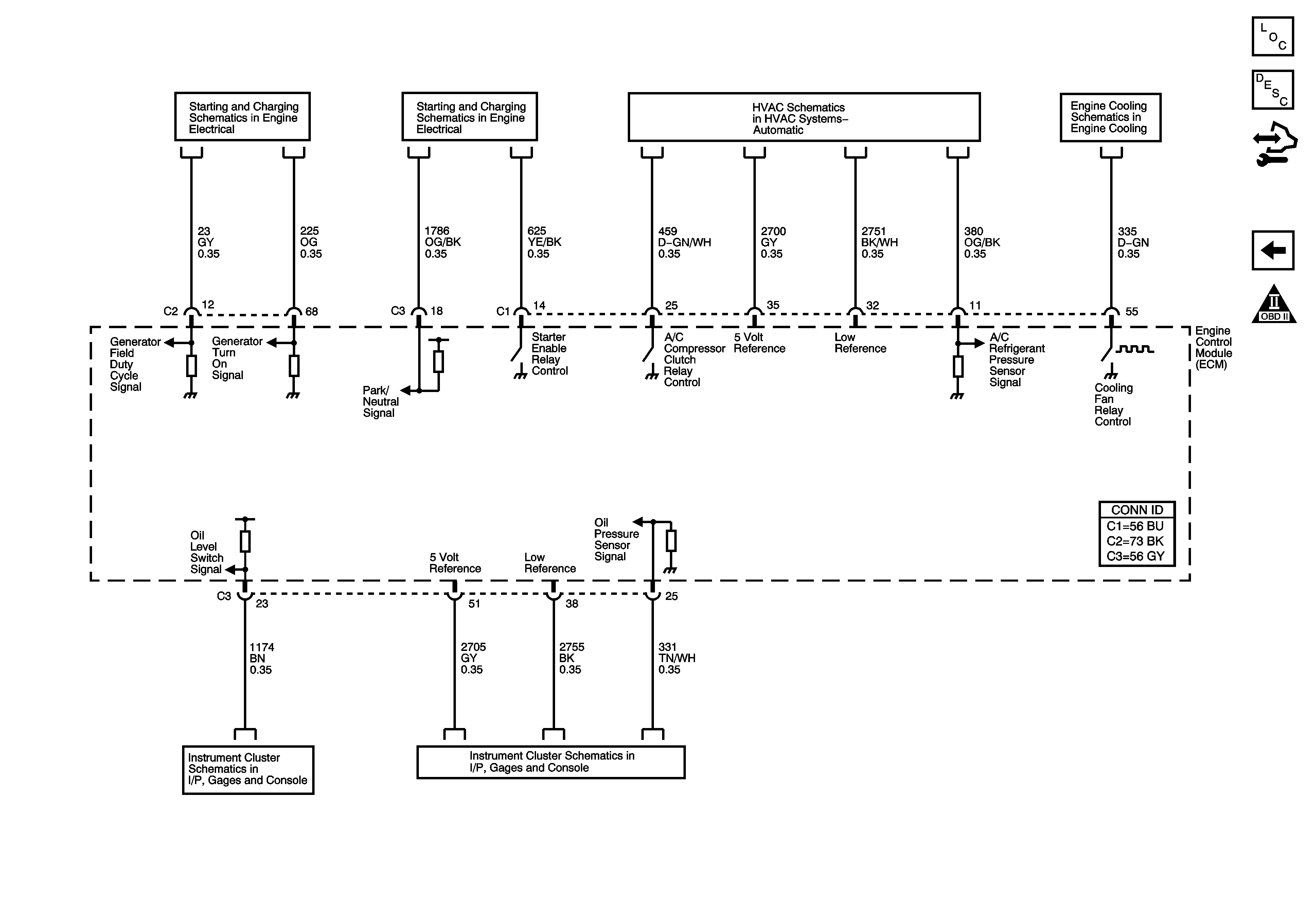
06 XLR Engine Controls 4.6L Schematics - Controlled/Monitored Subsystem References
Fuel Controls - EVAP Controls
Engine Controls Schematic Icons
Gages
Fuse Block - Underhood Bussing
Low Reference Bussing
G102
G302, G401, and G402
Figure 14:

Controlled/Monitored Subsystem References


Object Number: 1480649  Size: FS
Master Electrical Component List
Engine Control Module Description
Control Module References
Fuel Pump Controls
Engine Controls Schematic Icons
Charging
Starting and Charging - Cranking Schematics (LC3)
Compressor Controls
LH2
Messages
Gages