DTC Descriptor
DTC P2261: Supercharger By-Pass Valve Stuck
Diagnostic Fault Information
Perform the
Diagnostic System Check - Vehicle
prior to using this diagnostic procedure.
Circuit/System Description
The engine control module (ECM) controls boost pressure by a pulse-width ground signal to the boost control solenoid. The boost control solenoid is normally an open valve. Under most conditions, the ECM commands the boost control solenoid to operate at
99-100 percent duty cycle. This keeps the solenoid valve closed and allows only inlet vacuum to control the position of the bypass valve. At idle, engine vacuum is applied to the upper side of the bypass valve actuator, counteracting spring tension
to hold the bypass valve open. As engine load is increased, engine vacuum is decreased, causing the spring in the bypass valve actuator to overcome the applied vacuum, closing the bypass valve and allowing the boost pressure to increase. The bypass valve starts
to close when the vacuum measures 250 mm Hg (10 in Hg) and is fully closed at 90 mm Hg (3.5 in Hg). When reduced boost pressure is desired, the ECM commands the boost control solenoid to operate at a 0 percent
duty cycle, but may command a partial duty cycle, approximately 62 percent, depending on the operating condition. This opens the solenoid valve and allows boost pressure to enter the bypass valve actuator at the lower side to counteract the spring tension,
opening the bypass valve and re-circulating excess boost pressure back into the supercharger inlet. Refer to
Boost Control System Diagnosis
for further information.
Conditions for Running the DTC
| • | DTCs P0096, P0097, P0098, P0102, P0103, P0107, P0108, P0111, P0112, P0113, P0116, P0117, P0118, P0125, P0128, P0335, P0336, P0401, P0405, P1182, P1183, P1184, and P1404 are not set. |
| • | The engine speed is greater than 550 RPM. |
| • | The intake air temperature is greater than -7°C (+19°F). |
| • | The engine coolant temperature is greater than 70°C (158°F). |
| • | DTC 2261 runs continuously when the above conditions are met. |
Conditions for Setting
The engine control module (ECM) has determined that the predicted airflow through the supercharger bypass valve is not within the range of a calculated threshold for more than 20 seconds.
Action Taken When the DTC Sets
DTC P2261 is a Type B DTC.
Conditions for Clearing the MIL/DTC
DTC P2261 is a Type B DTC.
Reference Information
Schematic Reference
Engine Controls Schematics
Connector End View Reference
Electrical Information Reference
DTC Type Reference
Diagnostic Trouble Code (DTC) Type Definitions
Scan Tool Reference
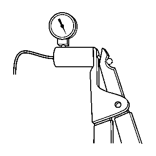
Special Tools Required
J 35555
Mityvac Metal
Circuit/System Verification
- If DTCs P0101, P0106, P0107, P0108, P0641, P0651, P1182, P1183, P1184 are set, refer to
Diagnostic Trouble Code (DTC) List - Vehicle
for further diagnosis.
- Ignition ON, observe the BARO, MAP, and SC Inlet Pressure parameters. All 3 sensor kPa values should be within 5 kPa of each other and also the actual barometric pressure (BARO). Determine the altitude for your area and compare the
parameters to the range specified in the altitude vs. barometric pressure table. Refer to
Altitude Versus Barometric Pressure
.
Caution: Refer to Road Test Caution in the Preface section.
- Engine running, on a road test perform a brief wide open throttle (WOT) acceleration from a stop. The MAP sensor parameter on the scan tool should increase rapidly. This increase should be from approximately 35 kPa at idle to more than 135 kPa.
- Ignition OFF, Inspect for the following conditions:
| • | The vacuum lines for any cracking, loose fit, and for the proper connections at the following: |
| - | The bypass valve actuator |
| - | The bypass valve solenoid |
| - | The supercharger intake plenum |
| • | The bypass valve actuator for sticking or damage |
| • | The boost control solenoid for damage |
| • | The bypass valve lever for damage |
Circuit/System Testing
Important: You must perform the Circuit System Verification before proceeding with Circuit/System Testing.
- Disconnect the inlet vacuum signal hose from the bypass valve actuator.
- Connect a vacuum gage to the inlet vacuum signal hose.
- Engine running, observe the vacuum gage. The reading should be more than 15 in Hg.
- Disconnect the boost signal hose from the bypass valve actuator.
- Connect a vacuum gage to the boost signal hose.
- Start and idle the engine in Park. Observe the vacuum gage. The reading should be 0 in Hg.
- Ignition OFF, connect the
J 35555
to the inlet vacuum signal port on the bypass valve actuator. Slowly apply vacuum to the valve while observing the bypass actuator. The bypass actuator rod should
retract.
| ⇒ | If the bypass actuator rod does not retract, disconnect the actuator from the bypass cable and apply vacuum to the actuator. If the actuator still does not retract, replace the actuator. |
| ⇒ | If the actuator valve retracts
after disconnecting the bypass cable, remove the supercharger and throttle body. Inspect the bypass cable and valve for a binding condition or a disconnected bypass valve. Refer to
Supercharger Cleaning and Inspection
. |
Caution: Refer to Road Test Caution in the Preface section.
- Engine running, on a road test take a snapshot of the induction data list while depressing the accelerator pedal to WOT, then releasing the throttle to the at rest position. Exit from the snapshot and review the data. Refer to
Scan Tool Snapshot Procedure
. The MAP sensor parameter on the scan tool should increase rapidly. This increase should be from approximately 35 kPa at idle to more than 130 kPa.
| ⇒ | If the MAP sensor parameter does not increase, remove the supercharger and throttle body. Inspect the bypass cable and brackets for the following conditions: |
Component Testing
- Ignition OFF, disconnect the top vacuum hose at the bypass actuator.
- Connect a vacuum gage to the actuator. Apply 10 in Hg to the actuator. The actuator should retract and hold vacuum for at least 15 seconds.
| ⇒ | If the actuator does not hold vacuum, replace the actuator. |
Repair Instructions
Perform the
Diagnostic Repair Verification
after completing the diagnostic procedure.
