For 1990-2009 cars only
Special Tools
J39765-A Fuel Sender Lock Ring Tool
Removal Procedure
- Disconnect the negative battery cable. Refer to Battery Negative Cable Disconnection and Connection .
- Remove the left fuel tank. Refer to Fuel Tank Replacement - Left Side .
- Place the fuel tank on a suitable work surface.
- Disconnect the fuel pump jumper harness from the fuel pump module.
- Disconnect the fuel feed line from the welded clip on the side of the fuel tank.
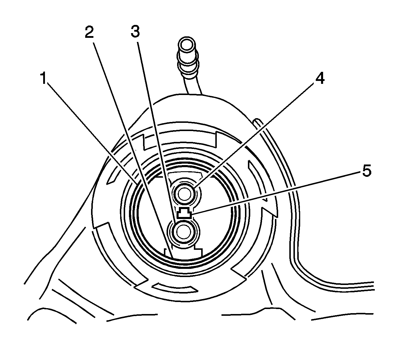
- Disconnect the jet line insert connector (2) from the crossover tube to the fuel tank opening.
- Using the J39765-A , remove the fuel pump module locking ring.
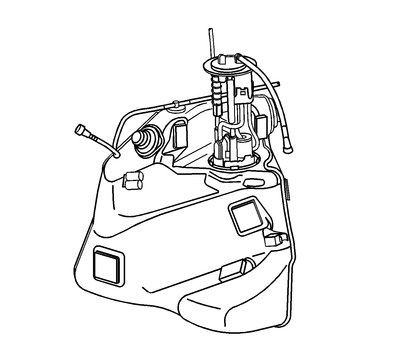
- Carefully remove the fuel pump module from the fuel tank, with the jet lines connected. Ensure not to damage the fuel sender float arm.
- Disconnect the jet line quick-connect connectors from the fuel pump module inner port.
- Remove the jet line from the module retainer cup. This line has no attached connector.
- Remove the fuel pump module O-ring from the fuel tank opening.
- Remove the jet line insert through the crossover tube to fuel tank opening.

Important: The fuel pump module is spring loaded and will spring upward when the locking ring is removed.

Installation Procedure
- Inspect the jet line insert for damage and replace if necessary.
- Install the jet line insert through the crossover tube to the fuel tank opening.
- Install a new fuel pump module O-ring to the fuel tank opening.
- Place tape around the jet line with the connector. This will permit line access once the pump module is inserted into the fuel tank.
- Install the pump module into the fuel tank half way , ensuring not to damage the float arm.
- Using the tape as a guide, gently pull the jet line up through the fuel pump module opening.
- Place the jet line with no connector in the module retainer cup.
- Secure the line into the module retaining clip.
- Remove the tape from the jet line with a connector.
- Connect the jet line quick-connect connectors to the fuel pump module inner port.
- Compress and align the fuel pump module into the fuel tank, while ensuring not to damage the float arm.
- Install the fuel pump module lock ring.
- Using the J39765-A , fully lock the fuel pump module lock ring in place.
- Connect the fuel supply line into the weld clip on the side of the fuel tank.
- Using a DMM, verify the full and empty readings resistance reading of the fuel pump module. Turn the fuel tank upside down to achieve the full tank reading.
- Connect the jet line insert connector (2) into the crossover tube to fuel tank opening.
- Connect the fuel pump jumper harness to the fuel pump module.
- Install the left fuel tank. Refer to Fuel Tank Replacement - Left Side .

Important: Pull on each connector to ensure that the connectors are properly latched.
Resistance
| • | Empty tank reading 247-253 Ω resistance |
| • | Full tank reading 38.5-41.05 Ω resistance |

Important: Pull the jet line insert connector to ensure that the insert is properly attached.
