Caution: Refer to Brake Dust Caution in the Preface section.
Removal Procedure
- Inspect the fluid level in the brake master cylinder reservoir.
- If the brake fluid level is midway between the maximum-full point and the minimum allowable level, no brake fluid needs to be removed from the reservoir before proceeding.
- If the brake fluid level is higher than midway between the maximum-full point and the minimum allowable level, remove brake fluid to the midway point before proceeding.
- Raise the vehicle and suitably support. Refer to Lifting and Jacking the Vehicle in General Information.
- Mark the relationship of the wheel to the axle flange.
- Remove the tire and wheel assembly. Refer to Tire and Wheel Removal and Installation in Tires and Wheels.
- Install a large C-clamp over the body of the brake caliper with the C-clamp ends against the rear of the caliper body and against the outer brake pad.
- Tighten the C-clamp until the caliper piston is compressed into the caliper bore enough to allow the caliper to slide past the brake rotor.
- Remove the C-clamp from the brake caliper.
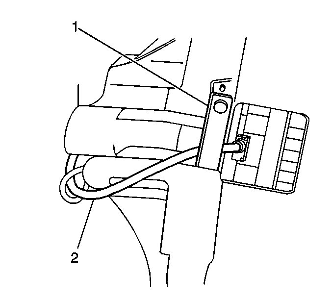
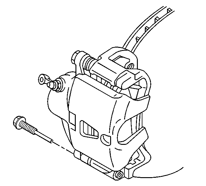
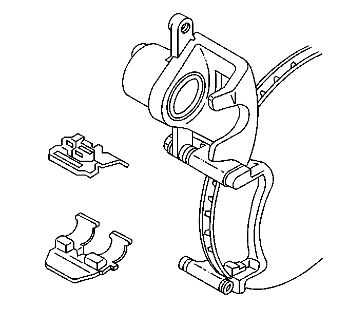
- Carefully lift the brake pad wear sensor wire retainer clip on the brake caliper (1) and remove the wire from under the clip.
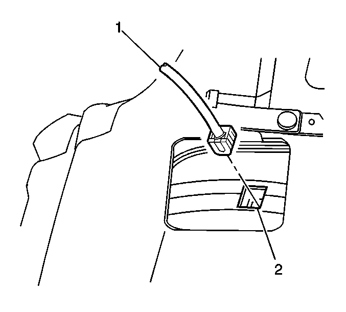
- Carefully hold the electronic pad wear sensor wire (1) snug, and with a small flat blade screw driver gently pry up on the electronic pad wear sensor to remove it from the inner brake pad (2).
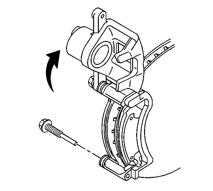
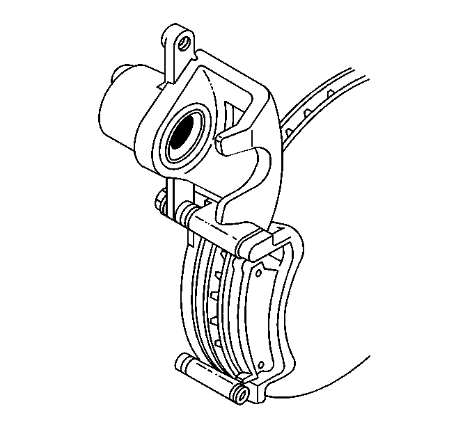
- Remove the bottom brake caliper pin bolt.
- Pivot the brake caliper body upward and secure out of the way with heavy mechanic's wire or equivalent. Do NOT disconnect the hydraulic brake flexible hose from the caliper.
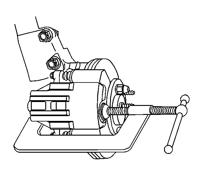
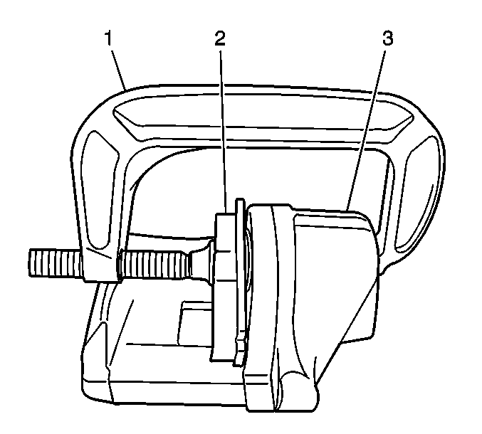
- Install a large C-clamp (1) over the body of the brake caliper (3) with the C-clamp ends against the rear of the caliper body (3) and against an old inner brake pad or a wood block (2) installed against the caliper piston.
- Tighten the C-clamp (1) until the caliper piston is compressed completely into the caliper bore.
- Remove the C-clamp (1) and the old brake pad or wood block (2) from the caliper (3).
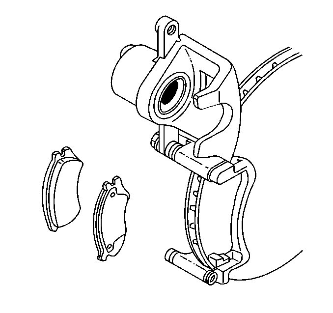
- Remove the inboard and outboard pads from the brake caliper bracket.
- Remove and inspect the brake pad retainers.
Important: Use care to not pinch the electronic pad wear sensor wiring harness (2), when disconnecting/connecting the electronic pad wear sensor.
Notice: Support the brake caliper with heavy mechanic wire, or equivalent, whenever it is separated from its mount and the hydraulic flexible brake hose is still connected. Failure to support the caliper in this manner will cause the flexible brake hose to bear the weight of the caliper, which may cause damage to the brake hose and in turn may cause a brake fluid leak.
Installation Procedure
Important: The electronic brake pad wear sensors must be replaced every time the brake pads are replaced. New brake pad wear sensors are included with GM replacement brake pad kits.
| • | Inspect the brake caliper bolt suspension boots for cuts, tears, or deterioration. If damaged, replace the pin boots. Refer to Front Disc Brake Hardware Replacement . |
| • | Inspect the brake caliper pin bolt for damage or corrosion. Replace if damaged or corroded. Do not attempt to clean away corrosion. Corrosion is typically caused by damaged pin boots. Refer to Front Disc Brake Hardware Replacement . |
| • | Inspect the piston boot for deterioration replace if damaged. Refer to Front Brake Caliper Overhaul . |
| • | Lubricate the front brake caliper pin bolts with a thin coat of NIGLUBE® grease . |
- Install the brake pad retainers into the brake caliper bracket.
- Install both brake pads into the brake caliper bracket.
- Pivot the brake caliper down over the brake pads and into the brake caliper bracket.
- Install the lower brake caliper pin bolt.
- Carefully push the electronic brake pad wear sensor (1) into the inner brake pad (2).
- Carefully lift the electronic brake pad wear sensor wire retainer clip on the brake caliper (1) and install the wire (2) under the clip.
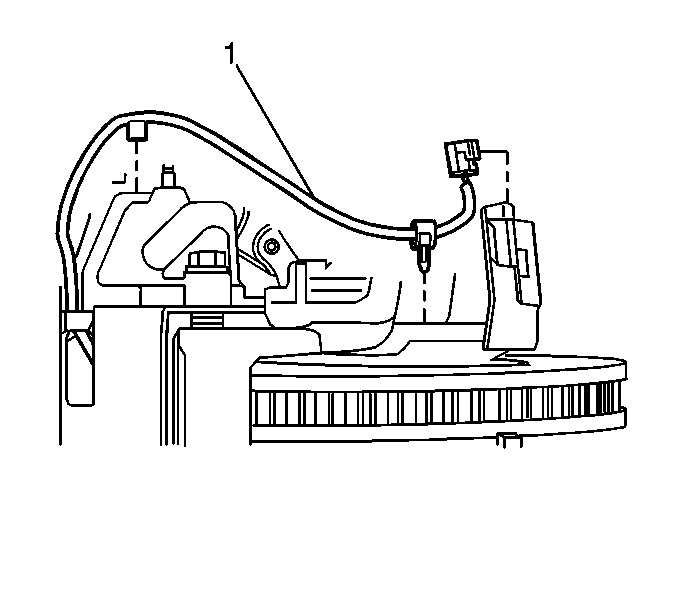
- Install the electronic brake pad wear sensor harness (1). The electronic brake pad wear sensor harness must be routed properly so that it will not be broken, cut or pinched.
- Install the tire and wheel assembly. Refer to Tire and Wheel Removal and Installation in Tire and Wheels.
- Lower the vehicle.
- With the engine OFF, gradually apply the brake pedal to approximately 2/3 of its travel distance.
- Slowly release the brake pedal.
- Wait 15 seconds, then repeat steps 10 - 11 until a firm brake pedal apply is obtained. This will properly seat the brake caliper pistons and brake pads.
- Fill the brake master cylinder reservoir to the proper level. Refer to Master Cylinder Reservoir Filling in Hydraulic Brakes.
- Burnish the pads and rotors. Refer to Brake Pad and Rotor Burnishing .
Notice: Use the correct fastener in the correct location. Replacement fasteners must be the correct part number for that application. Fasteners requiring replacement or fasteners requiring the use of thread locking compound or sealant are identified in the service procedure. Do not use paints, lubricants, or corrosion inhibitors on fasteners or fastener joint surfaces unless specified. These coatings affect fastener torque and joint clamping force and may damage the fastener. Use the correct tightening sequence and specifications when installing fasteners in order to avoid damage to parts and systems.
Tighten
Tighten the brake caliper pin bolt to 85 N·m (63 lb ft).
Important: Care must be taken that the electronic brake pad wear sensor harness is routed properly, to avoid damaging the harness.