GM Service Manual Online
For 1990-2009 cars only
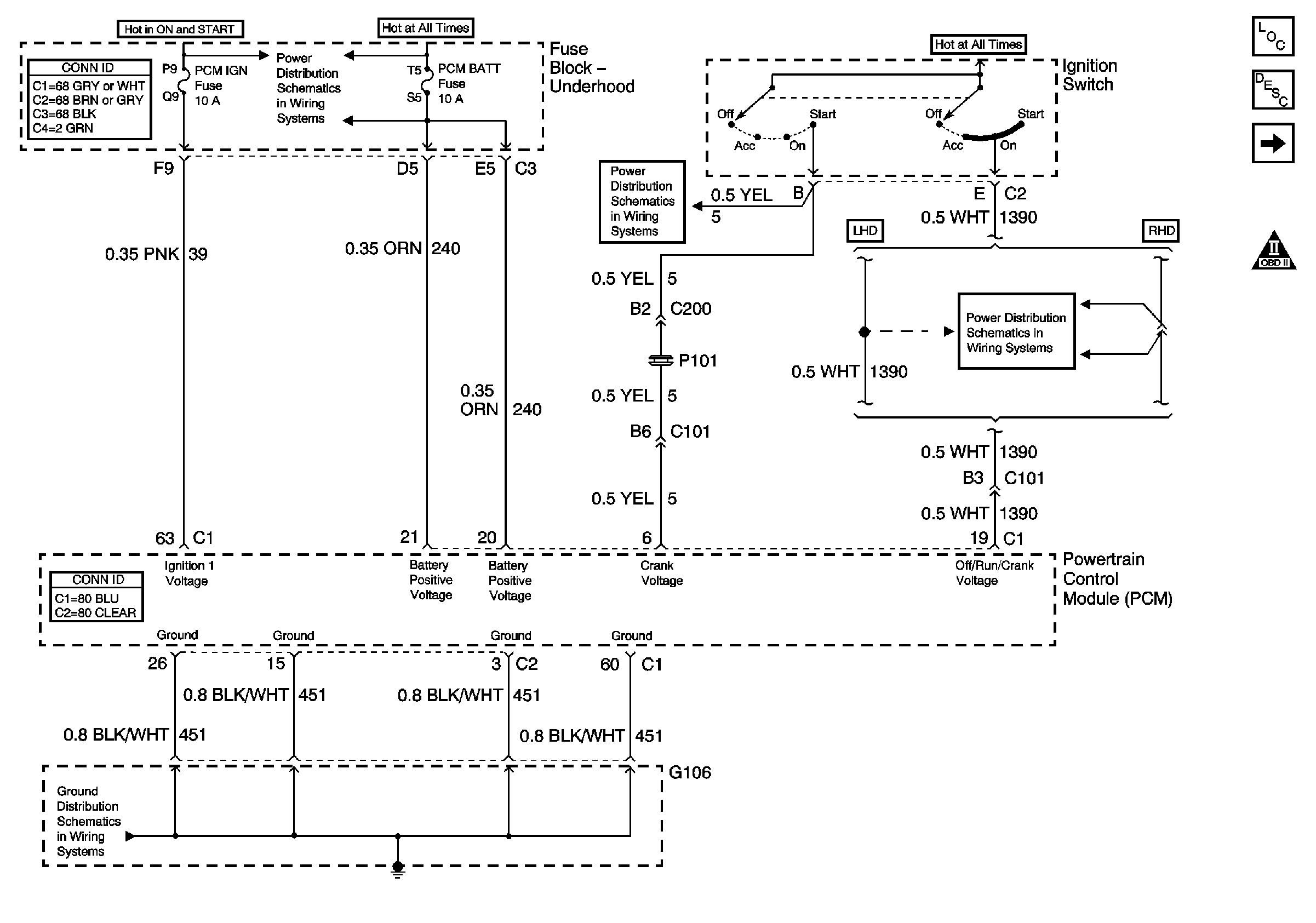
Figure 1:

PCM Power and Grounds


Object Number: 641930  Size: FS
Power to Underhood Fuse Block
Ignition Switch
Ignition Switch
G106 and G108
MIL Control and DLC
Engine Controls Component Views
OBD II Symbol Description Notice
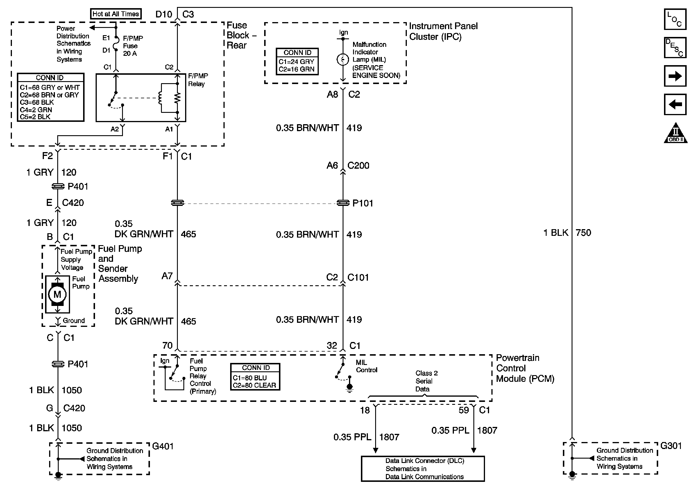
Figure 2:

Fuel Pump and MIL


Object Number: 641934  Size: FS
PCM Power and Grounds
Fuel Injectors
Engine Controls Component Views
OBD II Symbol Description Notice
Fuel System Description
Battery Feeds
G401 (1 of 3)
Class 2 Serial Data Line (LH Drive) (1 of 2)
G301
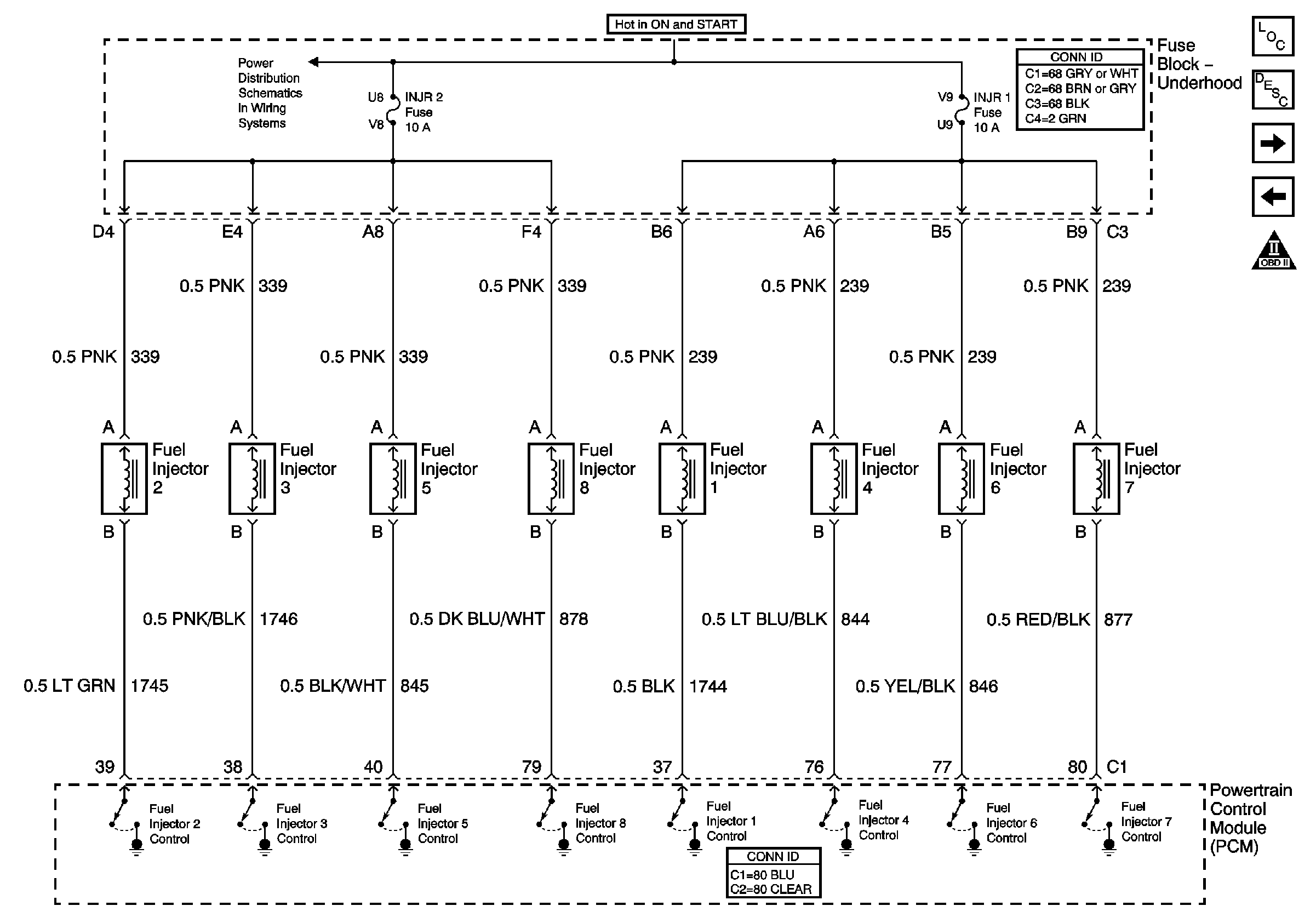
Figure 3:

Fuel Injectors


Object Number: 641935  Size: FS
Fuel Pump and MIL
Sensor Signals
Engine Controls Component Views
OBD II Symbol Description Notice
Fuel System Description
Power to Underhood Fuse Block
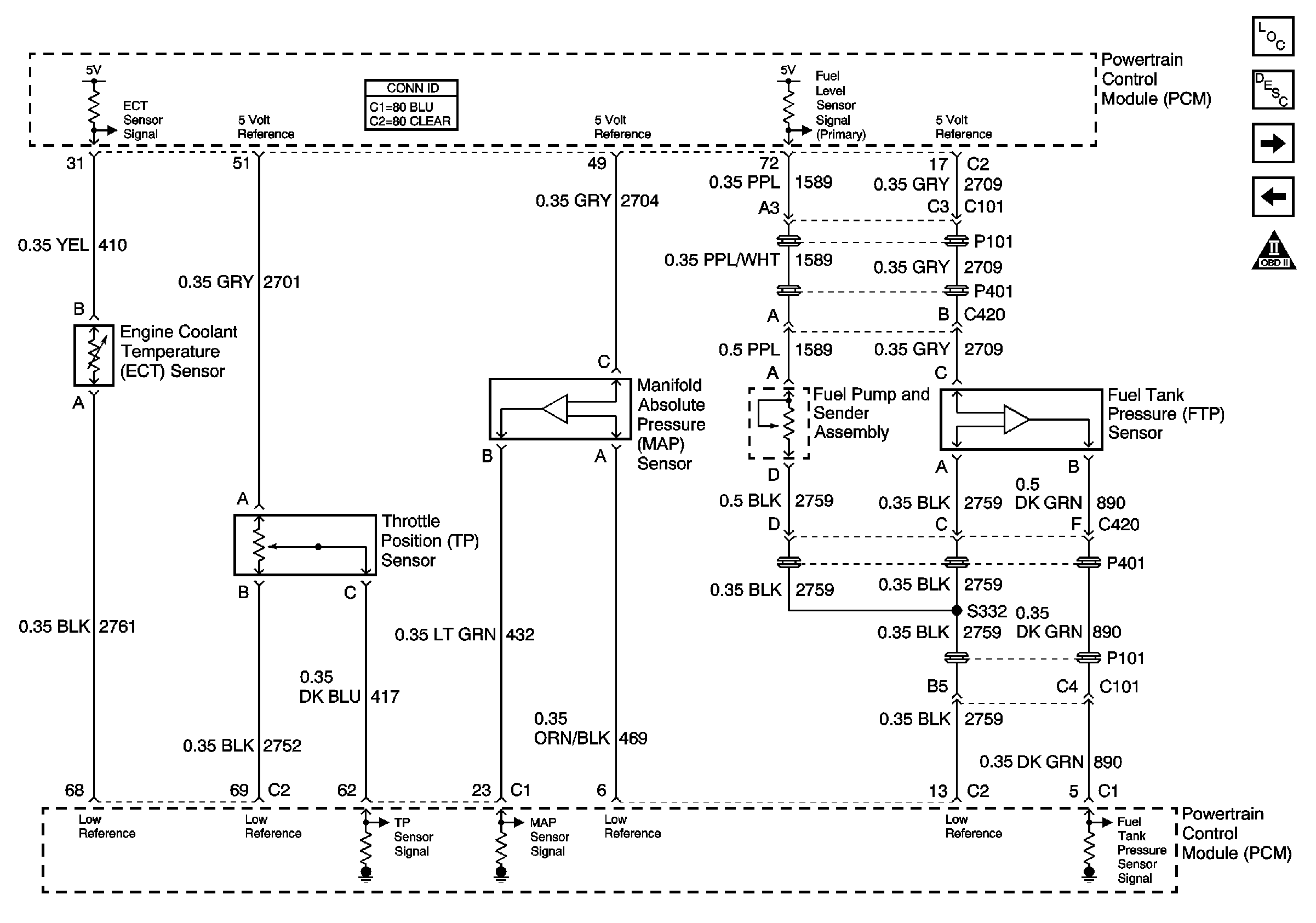
Figure 4:

Sensor Signals


Object Number: 641936  Size: FS
Fuel Injectors
Heated Oxygen Sensors (HO2S)
Engine Controls Component Views
OBD II Symbol Description Notice
Evaporative Emission Control System Description
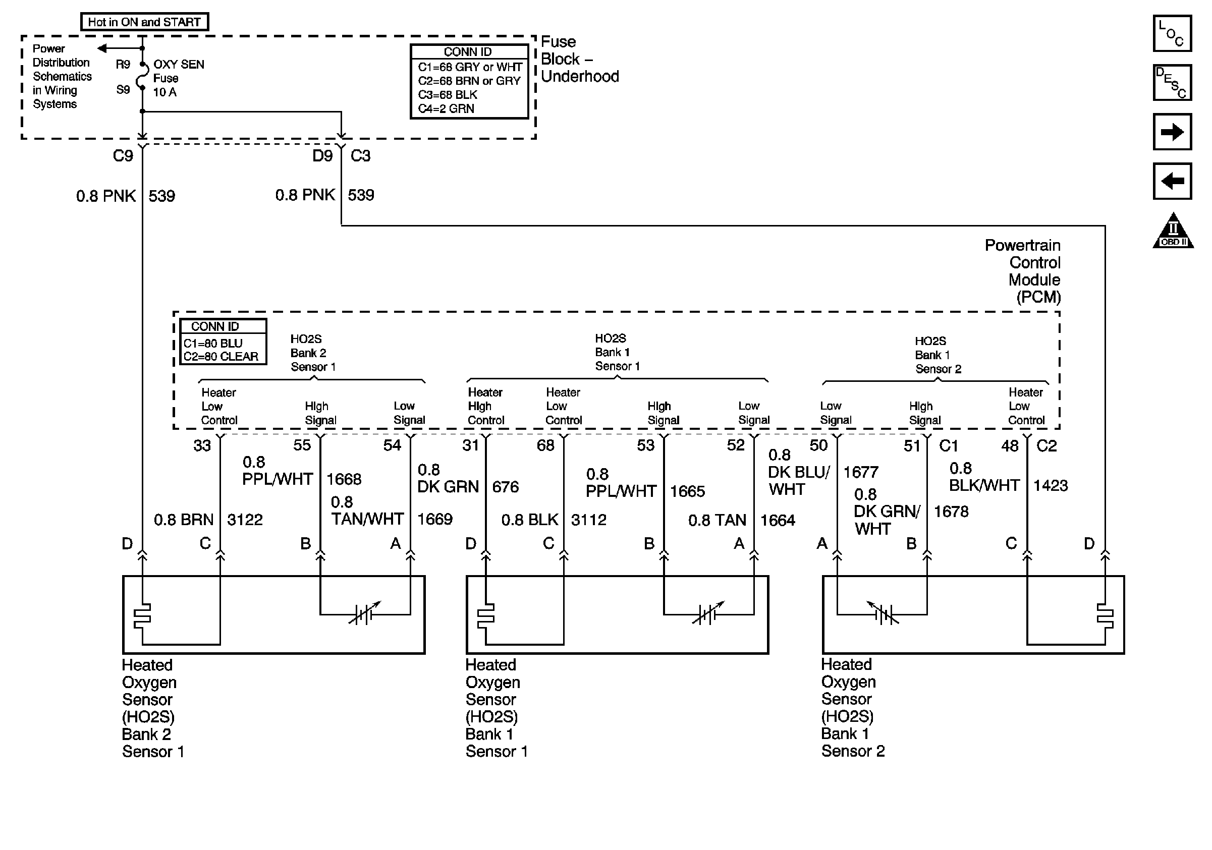
Figure 5:

Heated Oxygen Sensors (HO2S)


Object Number: 641937  Size: FS
Sensor Signals
EVAP and EGR Signals
Engine Controls Component Views
OBD II Symbol Description Notice
Powertrain Control Module Description
Power to Underhood Fuse Block
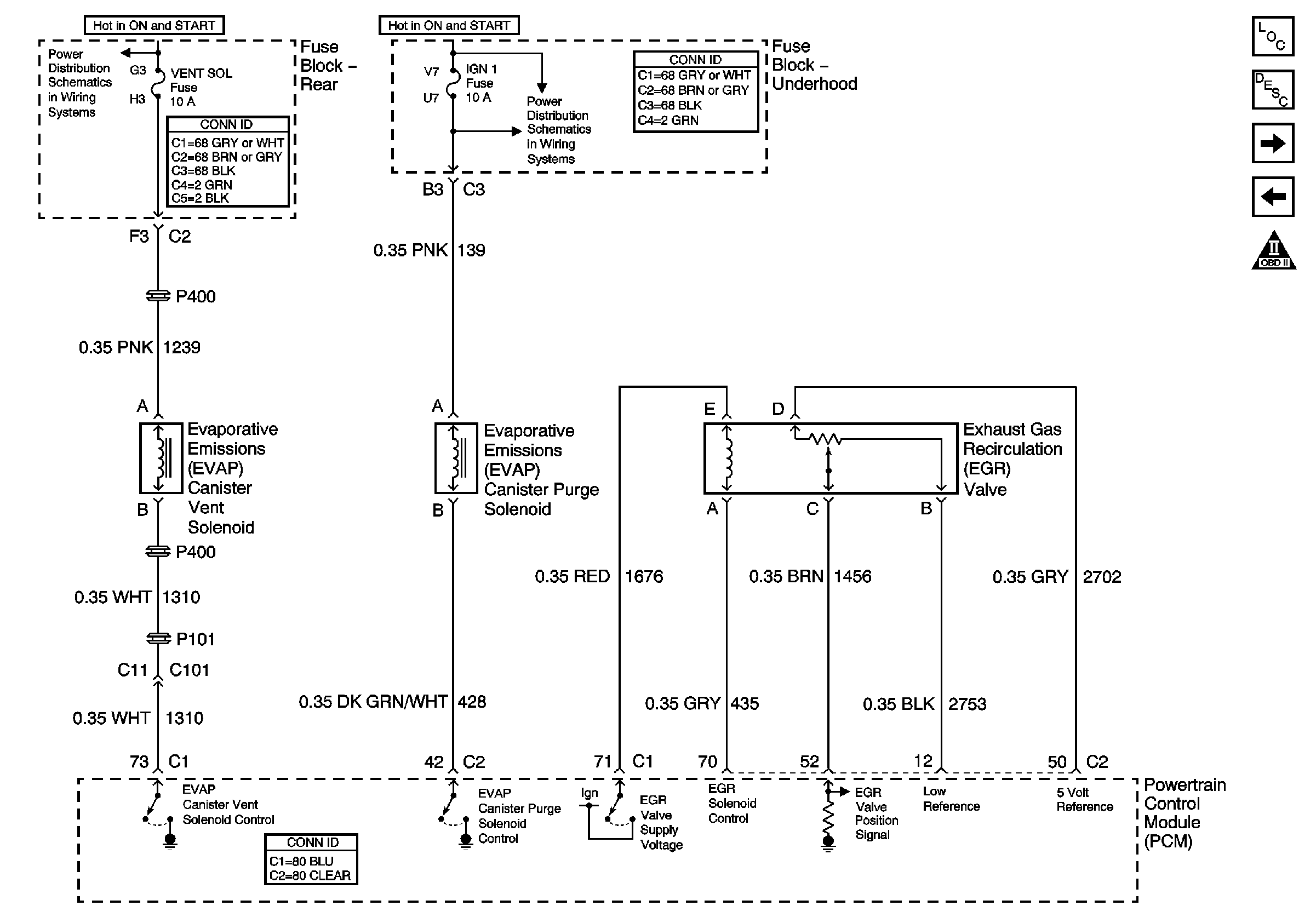
Figure 6:

EVAP and EGR Signals


Object Number: 641938  Size: FS
Heated Oxygen Sensors (HO2S)
MAF and IAC Signals
Engine Controls Component Views
OBD II Symbol Description Notice
Evaporative Emission Control System Description
Battery Feeds
Power to Underhood Fuse Block
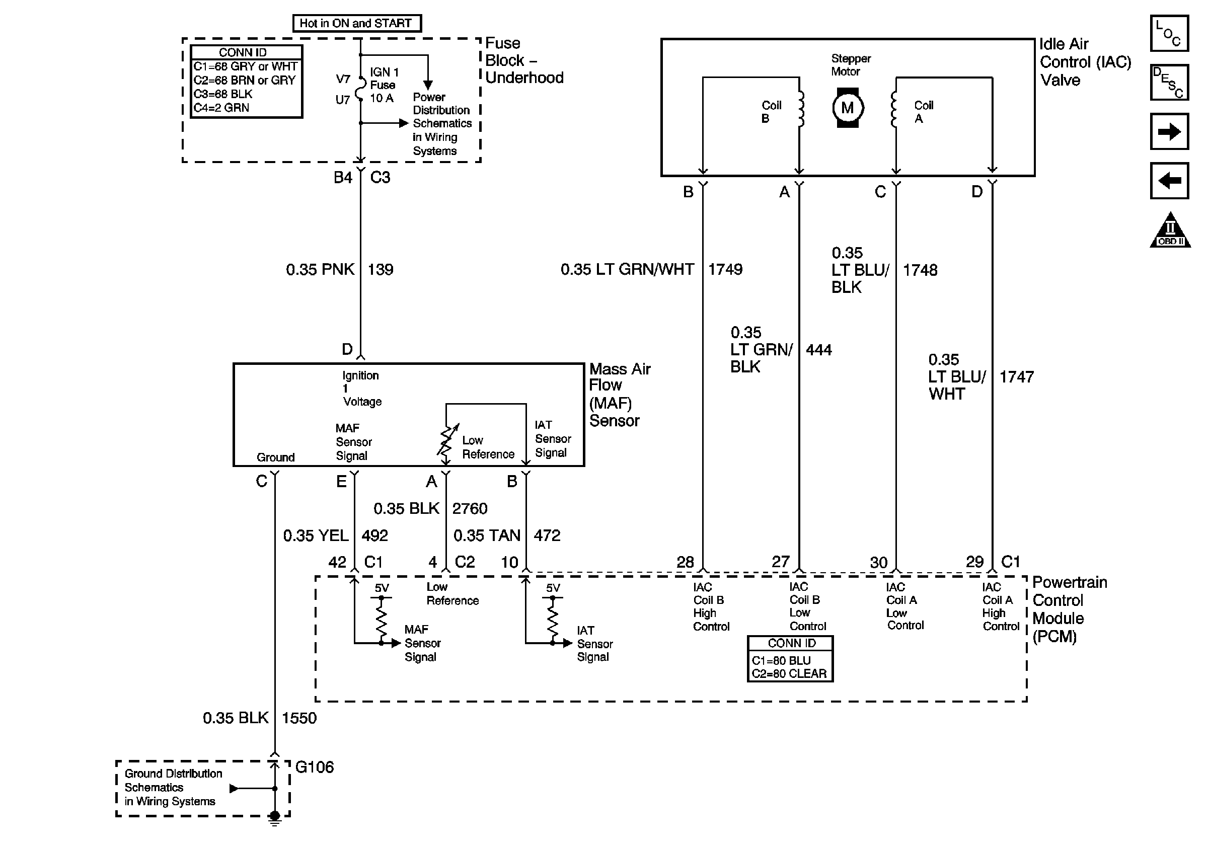
Figure 7:

MAF and IAC Signals


Object Number: 641939  Size: FS
EVAP and EGR Signals
PCM Inputs/Outputs (1 of 2)
Engine Controls Component Views
OBD II Symbol Description Notice
Powertrain Control Module Description
Power to Underhood Fuse Block
G106 and G108
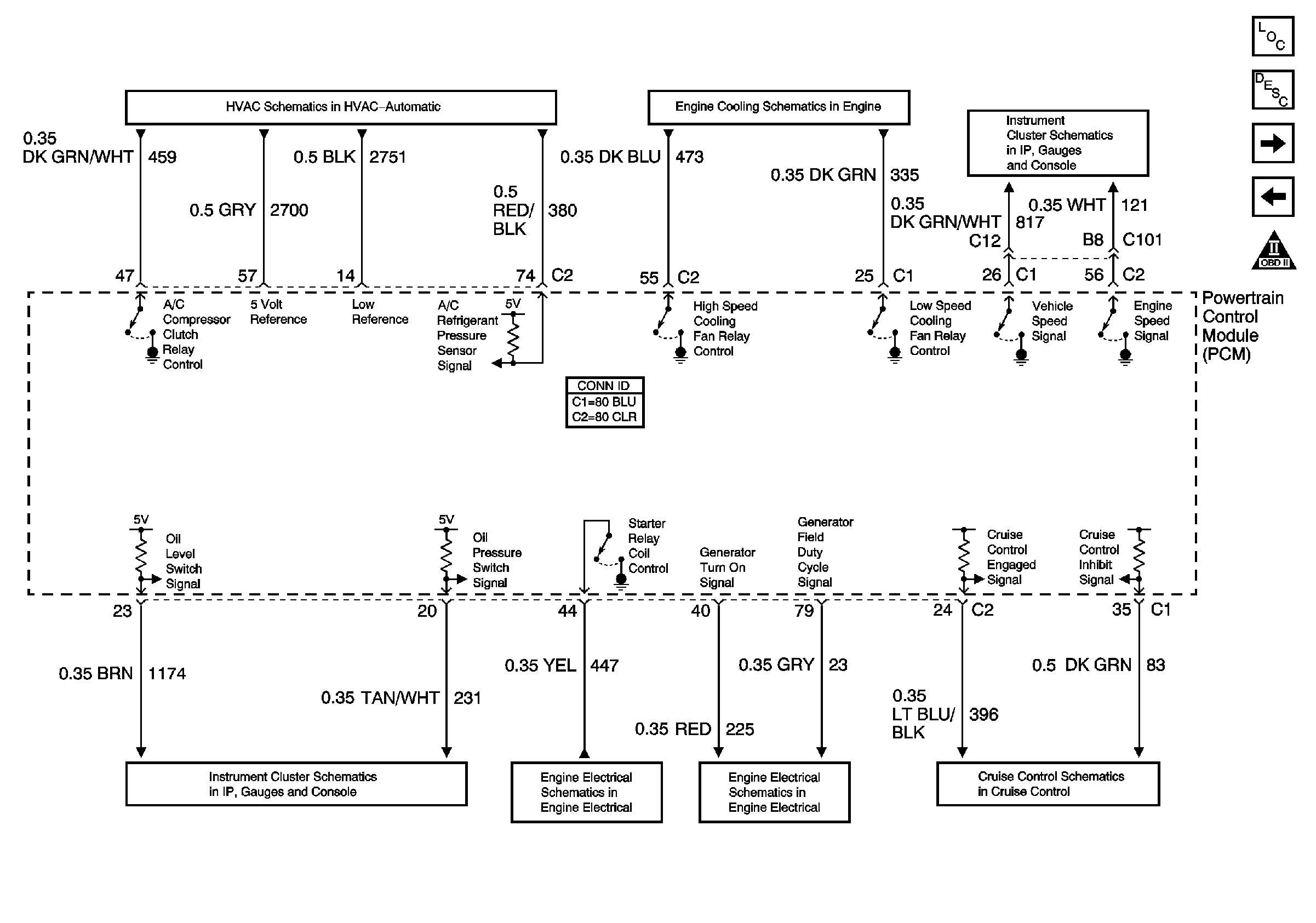
Figure 8:

PCM Inputs/Outputs (1 of 2)


Object Number: 641940  Size: FS
MAF and IAC Signals
PCM Inputs/Outputs (2 of 2)
Engine Controls Component Views
OBD II Symbol Description Notice
Powertrain Control Module Description
A/C Compressor Clutch
Cooling Fans
PCM Signals
PCM and IPM Signals
Starting Controls
Generator Controls
Cruise Control Module PCM Controls and Vehicle Speed Input
Figure 9:

PCM Inputs/Outputs (2 of 2)


Object Number: 641941  Size: FS
PCM Inputs/Outputs (1 of 2)
Ignition Control Module (ICM) Bank 1
Engine Controls Component Views
OBD II Symbol Description Notice
Powertrain Control Module Description
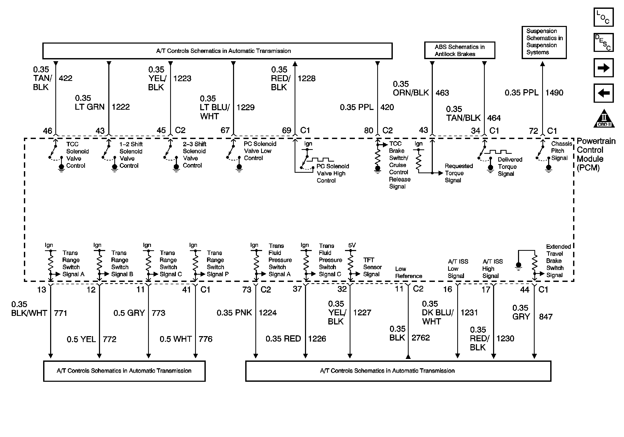
TCC/Cruise Release Switch and Transaxle Solenoids
Suspension Inputs (w/F45), Class 2, Traction Control, and Variable Effort Steering
Power and Ground
Automatic Transaxle Fluid Pressure Manual Valve Position Switch and VSS
Transaxle Sensors
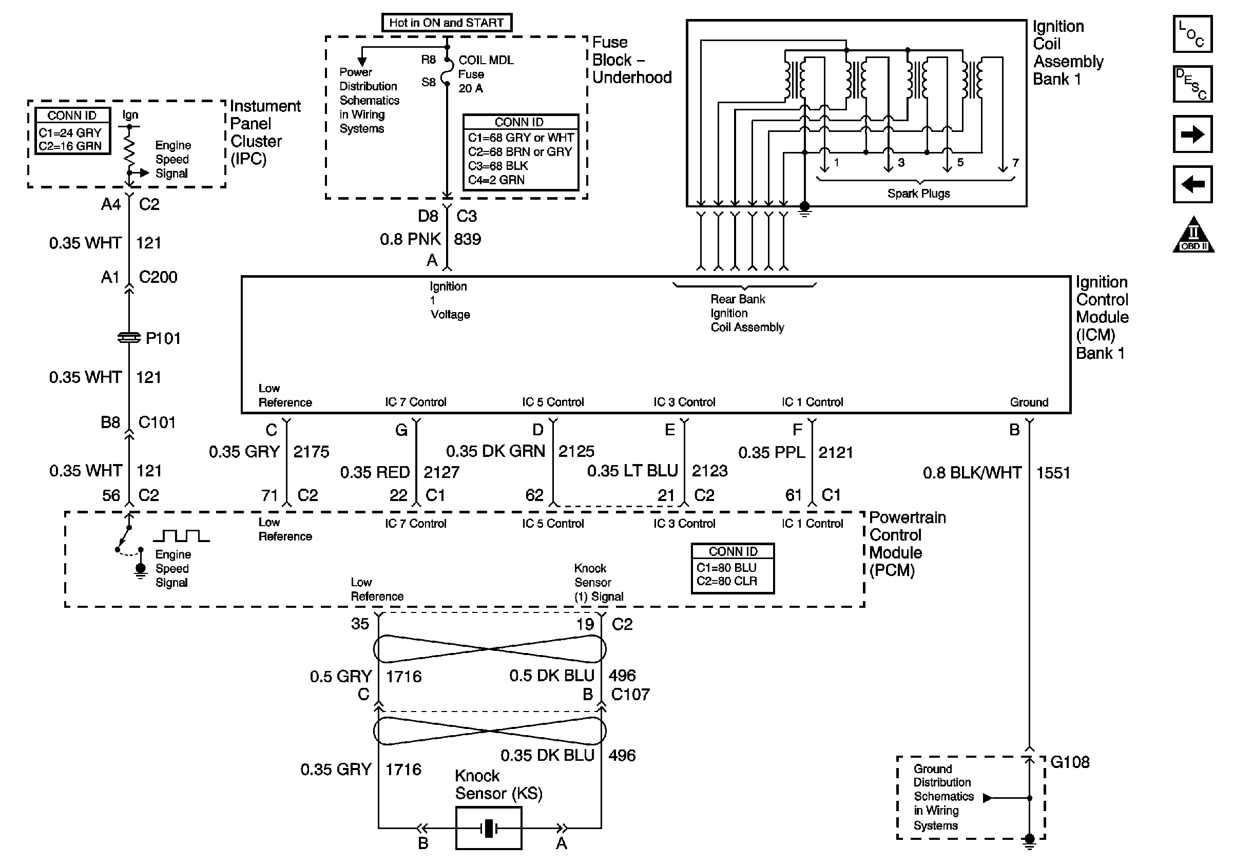
Figure 10:

Ignition Control Module (ICM) Bank 1


Object Number: 641949  Size: FS
PCM Inputs/Outputs (2 of 2)
Ignition Control Module (ICM) Bank 2
Engine Controls Component Views
OBD II Symbol Description Notice
Knock Sensor (KS) System Description
Power to Underhood Fuse Block
G106 and G108
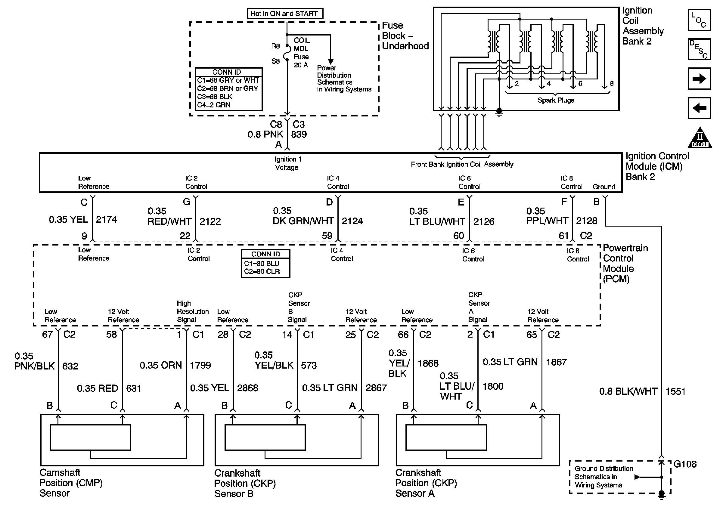
Figure 11:

Ignition Control Module (ICM) Bank 2


Object Number: 641947  Size: FS
Ignition Control Module (ICM) Bank 1
Secondary Air Injection (AIR) w/NB6 California Emissions
Engine Controls Component Views
OBD II Symbol Description Notice
Powertrain Control Module Description
Power to Underhood Fuse Block
G106 and G108
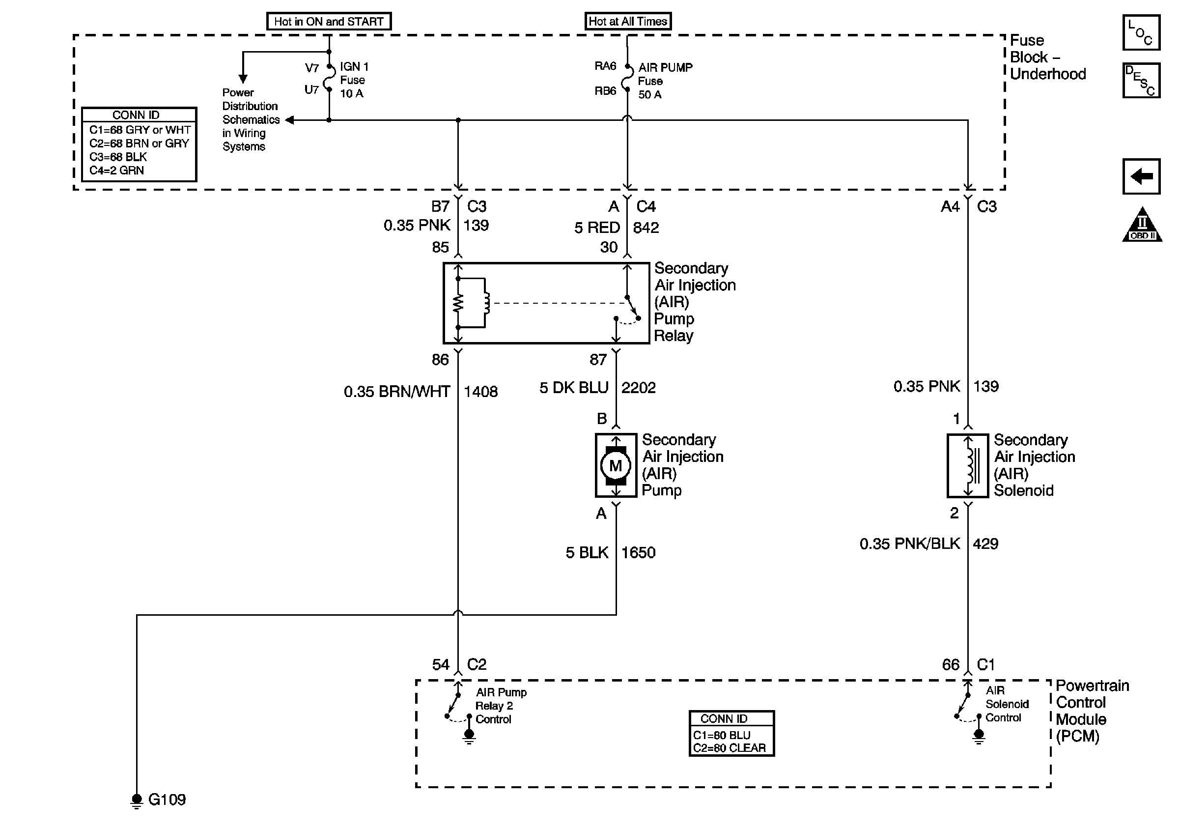
Figure 12:

Secondary Air Injection (AIR) w/NB6 California Emissions


Object Number: 641953  Size: FS
Ignition Control Module (ICM) Bank 2
Engine Controls Component Views
OBD II Symbol Description Notice
Secondary Air Injection System Description
Power to Underhood Fuse Block