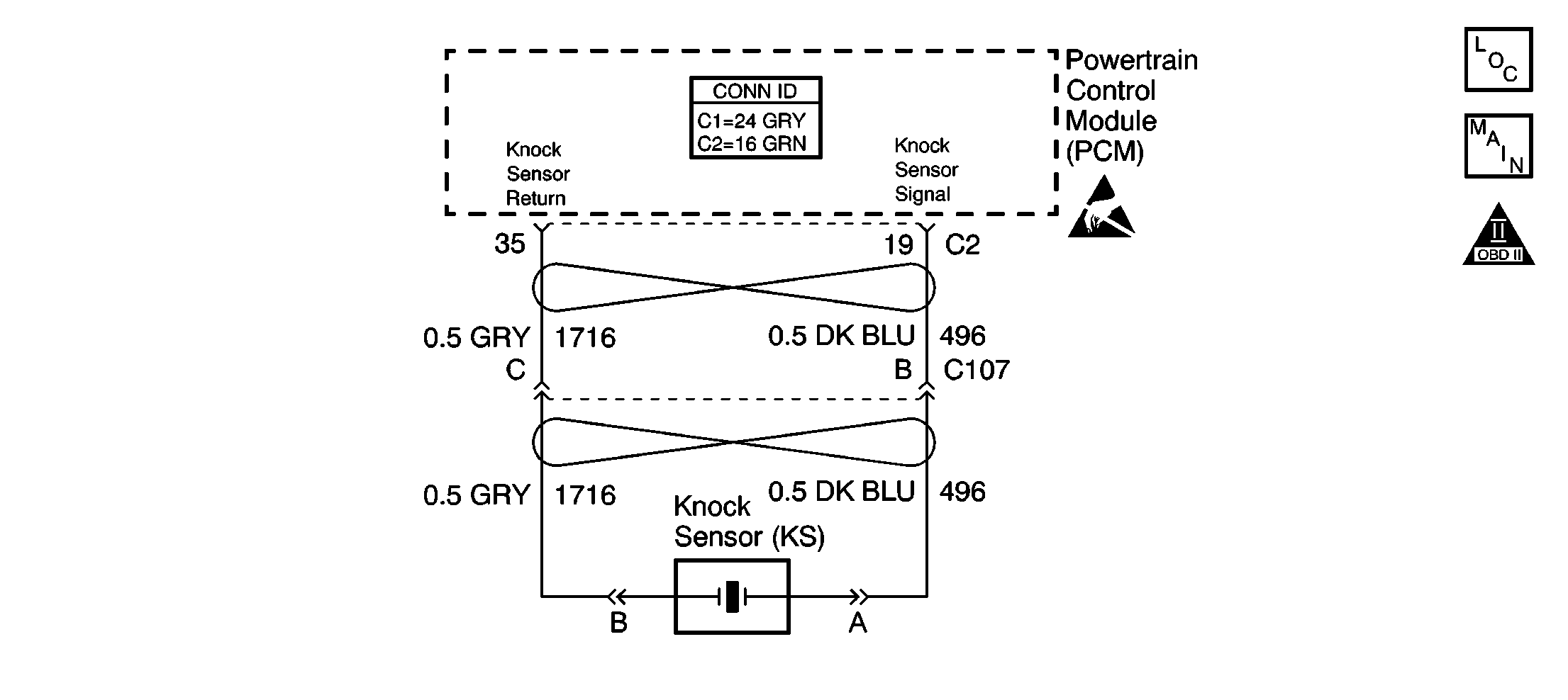
GM Service Manual Online
For 1990-2009 cars only

Object Number: 603350  Size: SF
Engine Controls Component Views
Ignition Control Module- Rear Bank
OBD II Symbol Description Notice
Handling ESD Sensitive Parts Notice

Circuit Description

The PCM uses a knock sensor (KS) to detect engine detonation (spark knock). The knock sensor produces an AC signal at all engine speeds, and loads. The PCM makes adjustments to the spark timing based on the amplitude and frequency of the KS signal.

A knock sensor module is no longer used to diagnose the knock sensor system. The circuitry is integrated into the PCM. The PCM uses the knock sensor to determine the amount of normal engine noise (noise channel) for a wide range of engine speeds and loads. The PCM compares the actual knock sensor signal to the learned noise channel. The PCM uses the noise channel to diagnose the knock sensor and related wiring. If the PCM detects a loss of the noise channel, DTC P0327 will set.

Conditions for Running the DTC

    • Engine speed is more than 3000 RPM.
    • ECT is more than 40°C (104°F)
    • System voltage is between 11 and 18 volts.
    • Throttle angle is more than 5 percent

Conditions for Setting the DTC

The PCM detects a KS signal less than 0.5 volt.

Action Taken When the DTC Sets

    • The PCM will not illuminate the malfunction indicator lamp (MIL).
    • The PCM will store the conditions present when the DTC set as Fail Records data.

Conditions for Clearing the MIL/DTC

    • The history DTC will clear after 40 consecutive warm-up cycles have occurred without a malfunction.
    • The DTC can be cleared using the scan tool Clear DTC Information function.

Diagnostic Aids

If the conditions is intermittent, refer to Intermittent Conditions .

Step

Action

Values

Yes

No

1

Did you perform the Powertrain On Board Diagnostic (OBD) System Check?

--

Go to Step 2

Go to Powertrain On Board Diagnostic (OBD) System Check

2

  1. Start the engine.
  2. Operate the vehicle within the Conditions for Running the DTC as specified in the supporting text.
  3. With the scan tool, monitor the Specific DTC Information for DTC P0327 until the test runs.

Does the scan tool indicate that DTC P0327 failed last test?

--

Go to Step 4

Go to Step 3

3

  1. Review and record the scan tool Fail Record Data.
  2. Operate the vehicle within the Fail Records conditions.
  3. With the scan tool, monitor the Specific DTC Information for DTC P0327 until the test runs.

Does the scan tool indicate that DTC P0327 failed last test?

--

Go to Step 4

Go to Diagnostic Aids

4

  1. Disconnect the knock sensor / starter solenoid harness connector, located on right side of engine compartment at rear corner of intake.
  2. With the DMM, measure the frequency between the KS signal and the KS ground circuits while tapping on the block with a non-metallic object.

Does the DMM display a fluctuating frequency while tapping on block?

--

Go to Step 5

Go to Step 6

5

  1. Turn ON the ignition, with the engine OFF.
  2. With the scan tool, save the Freeze Frame and Failure Records data stored when the DTC set.
  3. Turn OFF the ignition.
  4. Disconnect PCM connector.
  5. With the DMM, measure the frequency between the KS signal and the KS ground circuits while tapping on the block with a non-metallic object.

Does the DMM display a fluctuating frequency while tapping on block?

--

Go to Step 8

Go to Step 7

6

  1. Remove intake manifold. Refer to Intake Manifold Replacement in Engine Mechanical.
  2. Test for the following conditions:
  3. • Open or short to ground/sensor ground in the KS signal circuit (between the harness connector and the knock sensor)
    • Signal circuit for a short to voltage
    • Open KS ground circuit (between the harness connector and the knock sensor)
    • Poor connections at the knock sensor. Refer to Testing for Intermittent Conditions and Poor Connections in Wiring Systems.
  4. If a condition is found, repair as necessary. Refer to Wiring Repairs in Wiring Systems.

Did you find and correct the condition?

--

Go to Step 11

Go to Step 9

7

Locate and repair the following circuit conditions between the harness connector and the PCM.

  1. Poor connections in the knock sensor / starter solenoid harness connector. Refer to Testing for Intermittent Conditions and Poor Connections in Wiring System.
  2. Open or short to ground/sensor ground in the KS signal circuit, PCM side of harness connector
  3. Open KS ground circuit, PCM side of harness connector. Check for short to voltage.

Is the action complete?

--

Go to Step 11

--

8

  1. Inspect for poor connections at the PCM. Refer to Testing for Intermittent Conditions and Poor Connections in Wiring Systems.
  2. If the condition is found, repair as necessary. Refer to Connector Repairs in Wiring Systems.

Did you find and correct the condition?

--

Go to Step 11

Go to Step 10

9

Replace the knock sensor. Refer to Knock Sensor Replacement .

Is the action complete?

--

Go to Step 11

--

10

Important: The replacement PCM must be programmed.

Replace the PCM. Refer to Powertrain Control Module Replacement/Programming .

Is the action complete?

--

Go to Step 11

--

11

  1. Review and record the scan tool Fail Record Data.
  2. Clear the DTCs
  3. Operate the vehicle within the parameters listed in the Conditions for Running the DTC.
  4. With the scan tool, monitor the Specific DTC Information for DTC P0327 until the test runs.

Does the scan tool indicate that DTC P0327 passed?

--

System OK

Go to Step 4