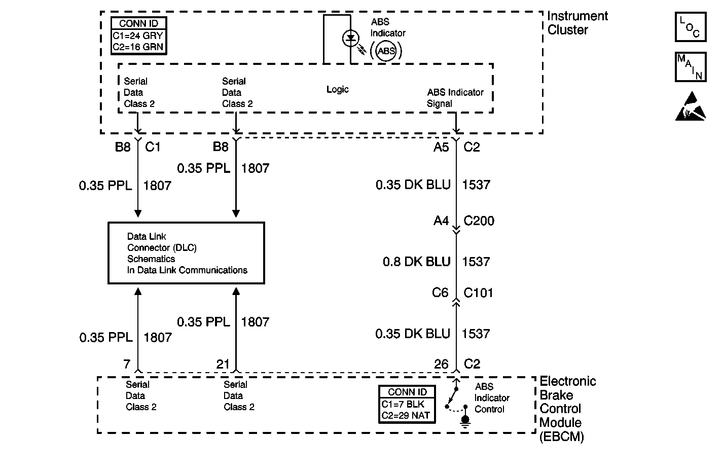
Circuit Description
The instrument cluster controls the operation of the ABS indicator. The electronic brake control module (EBCM) reports the desired status of the ABS indicator via serial data messages. The ABS indicator signal circuit is a back-up reporting circuit to the serial data messages. The EBCM supplies ground through the circuit when the ABS is operating properly. When there is a problem with ABS that should turn on the ABS indicator, the EBCM opens the ABS indicator signal circuit. If there is a problem with the ABS serial data messages, the instrument cluster uses the ABS indicator signal to determine if the ABS indicator should be illuminated. Using the serial data messages and back-up circuit, the instrument cluster decides whether to turn on the ABS indicator.
Test Description
The numbers below refer to the step numbers on the diagnostic table.
-
This test uses the scan tool to check the normal state of the ABS indicator control.
-
This test ensures that the instrument cluster can operate the ABS indicator.
Step | Action | Value(s) | Yes | No | ||||||
|---|---|---|---|---|---|---|---|---|---|---|
1 | Did you perform the ABS Diagnostic System Check? | -- | Go to Step 2 | |||||||
2 | Inspect the EBCM ground, making sure the ground is clean and torqued to the proper specification. Refer to Circuit Testing and Wiring Repairs in Wiring Systems. Did you find and correct the condition? | -- | Go to Step 9 | Go to Step 3 | ||||||
With a scan tool, observe the ABS Warning Indicator parameter in the DRP/ABS/TCS data list. Does the scan tool display Off? | -- | Go to Step 4 | Go to Step 5 | |||||||
Does the ABS indicator illuminate during the bulb check and then turn OFF? | -- | Go to Step 5 | Go to Step 6 | |||||||
5 | Inspect for poor connections at the harness connector of the EBCM. Refer to Testing for Intermittent Conditions and Poor Connections and Connector Repairs in Wiring Systems. Did you find and correct the condition? | -- | Go to Step 9 | Go to Step 7 | ||||||
6 | Inspect for poor connections at the harness connector of the instrument cluster (IPC). Refer to Testing for Intermittent Conditions and Poor Connections and Connector Repairs in Wiring Systems. Did you find and correct the condition? | -- | Go to Step 9 | Go to Step 8 | ||||||
7 |
Important: Perform the setup procedure for the EBCM. An unprogrammed EBCM will
result in the following conditions:
Replace the EBCM. Refer to Electronic Brake Control Module Replacement . Did you complete the repair? | -- | Go to Step 9 | -- | ||||||
8 | Replace the instrument cluster (IPC). Refer to Instrument Cluster Replacement in Instrument Panel, Gauges and Console. Did you complete the repair? | -- | Go to Step 9 | -- | ||||||
9 | Operate the system in order to verify the repair. Did you correct the condition? | -- | System OK | Go to Step 2 |
