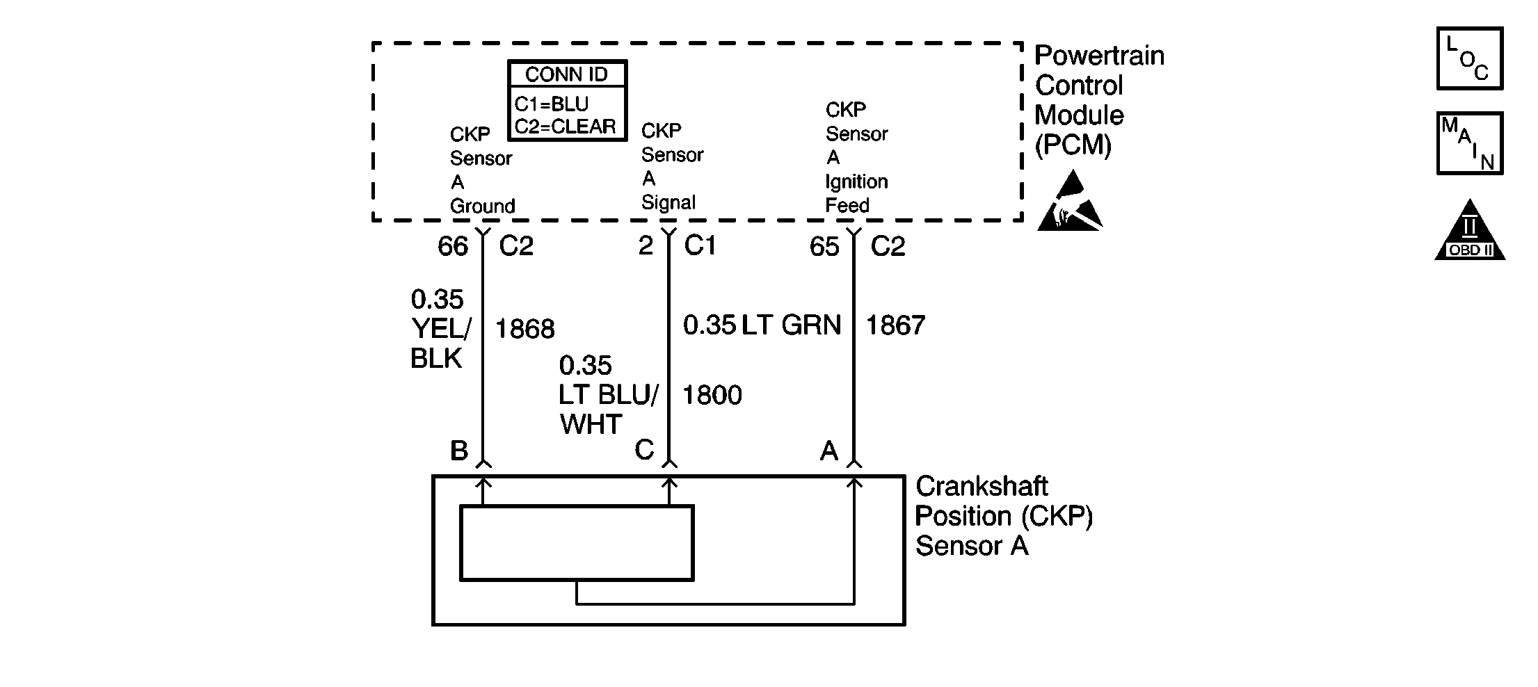
Circuit Description
The PCM uses dual crankshaft position (CKP A and CKP B) sensors to determine crankshaft position. The PCM supplies an ignition voltage and a ground for each sensor. During engine rotation, a slotted ring, machined into the crankshaft, causes the sensors to return a series of ON and OFF pulses to the PCM. The PCM uses these pulses to decode the position of the engine crankshaft.
The PCM uses two basic methods of decoding the engine position: Angle Based and Time Based (using either CKP A or CKP B sensor input). During normal operation, the PCM uses the angle based method. In order to operate in this mode, the PCM must receive signal pulses from both CKP sensors. The PCM uses the signal pulses to determine an initial crankshaft position, and to generate MEDRES (24X reference) and LORES (4X reference) signals. Once the initial crank position is determined, the PCM continuously monitors both sensors for valid signal inputs. As long as both signal inputs remain, the PCM will continue to use the angle based mode.
When either CKP signal is lost, the PCM will compare the MEDRES signal to the camshaft position (CMP) sensor signal. If the PCM detects a valid CMP signal, and the MEDRES to CMP signal correlation is correct, the PCM determines that CKP sensor A is at fault. However, if the MEDRES to CMP correlation is incorrect, the PCM determines that CKP sensor B is at fault. If the PCM determines that CKP sensor A is at fault, DTC P0335 will set. The PCM will switch from angle based mode to Time Based mode B using CKP sensor B signal input.
Conditions for Running the DTC
The engine is cranking or running.
Conditions for Setting the DTC
The PCM detects a loss of CKP sensor A signal.
Action Taken When the DTC Sets
| • | The PCM illuminates the malfunction indicator lamp (MIL) during the second consecutive trip in which the diagnostic test runs and fails. |
| • | The PCM stores the conditions present when the DTC set as Freeze Frame/Failure Records data. |
Conditions for Clearing the MIL/DTC
| • | The PCM will turn the MIL OFF after the third consecutive trip in which the diagnostic runs and passes. |
| • | The history DTC will clear after 40 consecutive warm-up cycles have occurred without a malfunction. |
| • | The DTC can be cleared by using the scan tool Clear DTC Information function. |
Diagnostic Aids
Ignition system DTCs set with the ignition in the START position if the starter relay or the starter is inoperative. When the PCM enables starter operation, the PCM also initiates the diagnostic test routines for DTCs P0335, P0340, and P0385. The PCM will not receive signal input from the CKP and CMP sensors if a condition exists which prevents the engine from cranking. When this occurs, the DTCs will set.
If DTC P0615 is set, diagnose DTC P0615 first. If DTC P0335, P0340, and/or P0385 are set and no trouble is found, check for the following conditions:
| • | Is there a no-crank condition or an intermittent no-crank condition? |
| • | Was an attempt made to crank the engine with the shift lever not in P/N? |
Procedures for Selecting Crank Position Sensing Decode Mode
When diagnosing the crankshaft position sensors, it may be necessary to enable a specific decode mode (Angle, Time A, or Time B). To enable a specific crank decode, using the scan tool, perform the following steps:
| • | Turn the ignition to the RUN/ON position. |
| • | Select Engine Output Controls. |
| • | Select Crank Position Sensing Decode Mode. |
| • | Select the desired mode (Angle, Time A, or Time B) by pressing SELECT STATE. |
| • | Command the decode mode by pressing COMMAND STATE. |
The commanded state remains valid for the current ignition cycle. A specific decode mode can not be commanded with the engine running, or after commanding a desired decode mode. To command a different decode mode, you must cycle the ignition OFF and ON.
Test Description
The numbers below refer to the step numbers on the diagnostic table.
-
This step determines if the ignition feed circuit to the CKP A, CKP B, and the CMP is shorted to a ground. If all three DTCs are set, this indicates the circuit is shorted to a ground or a sensor is internally shorted. All three DTCs set because the ignition feed circuits are internally connected within the PCM. The engine will not start with this condition.
-
DTC P0386 indicates an intermittent loss of CKP sensor B signal while in Time B mode. DTC P0386 only sets after the PCM detects a loss of CKP sensor A signal and has switched to Time B mode.
During normal operation, the PCM uses the Angle Mode to determine engine position. In order to operate in this mode, the PCM must receive valid input from both CKP sensors. If the PCM detects a loss of CKP sensor A signal, the PCM switches to a Time B mode using CKP sensor B input to determine engine position. If the PCM detects a loss of CKP sensor B, the PCM switches to a Time A mode using CKP sensor A input to determine engine position.
-
During engine operation, if moving the harnesses and connectors related to CKP sensor A results in a switch to Time B mode, may also cause an engine stall condition, an intermittent condition in the harnesses or connectors is present. If the harnesses and connectors are OK, CKP sensor A may be the cause of the intermittent condition.
-
In order to test the CKP sensor A signal circuit, the PCM must be commanded to Time A mode using the scan tool. This allows the PCM to monitor input signals from CKP sensor A. Refer to Diagnostic Aids for the procedures to selecting the Crank Decode Mode.
-
This step determines if the CMP sensor is shorted internally. If the 12 Volt Reference parameter changes from Fault to OK, the condition is with the sensor.
-
This step determines if the CKP A sensor is shorted internally. If the 12 Volt Reference parameter changes from Fault to OK, the condition is with the sensor.
-
This step determines if the CKP B sensor is shorted internally. If the 12 Volt Reference parameter changes from Fault to OK, the condition is with the sensor.
Step | Action | Values | Yes | No |
|---|---|---|---|---|
1 | Did you perform the Powertrain On Board Diagnostic (OBD) System Check? | -- | Go to Step 2 | |
Are DTCs P0335, P0340, and P0385 set? | -- | Go to Step 11 | Go to Step 3 | |
|
Important: If DTC P0386 is also set, continue with the diagnostic table for DTC P0335 before diagnosing DTC P0386.
Does the scan tool indicate the CKP sensor status as ANGLE? | -- | Go to Step 4 | Go to Step 5 | |
Did you find and correct the condition? | -- | Go to Step 21 | Go to Diagnostic Aids | |
5 |
Does the test lamp illuminate? | -- | Go to Step 6 | Go to Step 8 |
6 | Connect the test lamp between the supply voltage circuit of the CKP A sensor and the ground circuit of the CKP A sensor. Does the test lamp illuminate? | -- | Go to Step 7 | Go to Step 9 |
Does the scan tool indicate an RPM while touching the test lamp to the signal circuit? | -- | Go to Step 15 | Go to Step 10 | |
8 |
Did you find and correct the condition? | -- | Go to Step 21 | Go to Step 16 |
9 |
Did you find and correct the condition? | -- | Go to Step 21 | Go to Step 16 |
10 |
Did you find and correct the condition? | -- | Go to Step 21 | Go to Step 16 |
Does the scan tool display OK? | -- | Go to Step 17 | Go to Step 12 | |
Does the scan tool display OK? | -- | Go to Step 18 | Go to Step 13 | |
Does the scan tool display OK? | -- | Go to Step 19 | Go to Step 14 | |
14 |
Did you find and correct the condition? | -- | Go to Step 21 | Go to Step 20 |
15 | Inspect for poor connections at the harness connector of the CKP A sensor. Refer to Testing for Intermittent Conditions and Poor Connections and Connector Repairs in Wiring Systems. Did you find and correct the condition? | -- | Go to Step 21 | Go to Step 18 |
16 | Inspect for poor connections at the harness connector of the PCM. Refer to Testing for Intermittent Conditions and Poor Connections and Connector Repairs in Wiring Systems. Did you find and correct the condition? | -- | Go to Step 21 | Go to Step 20 |
17 | Replace the CMP sensor. Refer to Camshaft Position Sensor Replacement . Is the replacement complete? | -- | Go to Step 21 | -- |
18 | Replace the CKP sensor A. Refer to Crankshaft Position Sensor Replacement . Is the replacement complete? | -- | Go to Step 21 | -- |
19 | Replace the CKP sensor B. Refer to Crankshaft Position Sensor Replacement . Is the replacement complete? | -- | Go to Step 21 | -- |
20 |
Important: The replacement PCM must be programmed. Replace the PCM. Refer to Powertrain Control Module Replacement/Programming . Is the replacement complete? | -- | Go to Step 21 | -- |
21 |
Does the scan tool display the DTC ran and passed? | -- | System OK | Go to Step 2 |
