Tools Required
| • | J 43013 Fuel
Injector Removal Tool/Battery |
Removal Procedure
Important: The fuel injector is serviced as a complete assembly only. If the fuel
injectors are found to be leaking, the engine oil may be contaminated with
fuel.
- Relieve the fuel pressure. Refer to
Fuel Pressure Relief
.
- Remove the fuel injector electrical connector from the fuel injector.
Important: It may be necessary to remove the fuel rail from the intake manifold
to allow increased fuel rail movement for injector access.
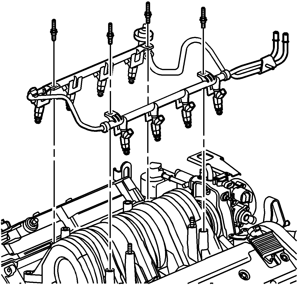
- Remove the fuel rail from the intake manifold. Refer to
Fuel Injection Fuel Rail Assembly Replacement
.
- Remove the fuel injector up out of intake manifold using J 43013
fuel injector removal
tool/battery between the bottom of injector and intake manifold.
Important: It may be necessary to release the adjacent injector from
the intake manifold to allow increased fuel rail movement for injector access.
- Spread the injector retainer clip to release injector from fuel rail.
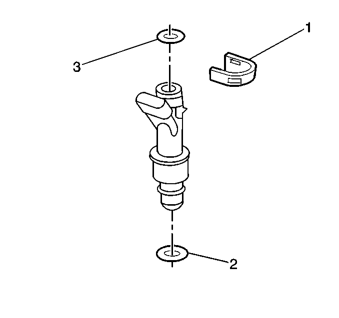
- Remove the fuel injector
assembly.
- Remove the fuel injector upper O-ring (3).
- Remove the fuel injector lower O-ring (2).
- Discard the injector O-ring seals.
Installation Procedure
Important: Fuel injector O-rings should always be replaced whenever fuel injectors
are serviced.
Each fuel injector is calibrated for a specific flow rate. Be sure to
use the correct part number when ordering replacement fuel injectors. Be sure
to reinstall the correct O-ring for fuel injector. If the sealing O-ring
is not seated properly, a vacuum leak is possible and driveability complaints
may occur.
- Lubricate the new upper
(3) and lower (2) O-rings with clean engine oil.
- Install the new upper (3) and lower (2) injector O-rings on the
fuel injector.
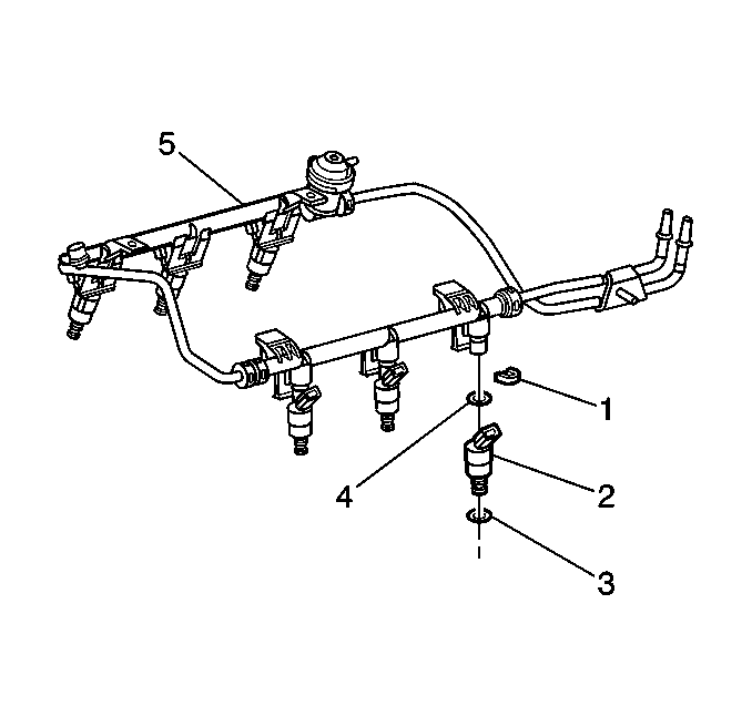
- Install the fuel injector
(2) on to fuel rail (5).
| • | Ensure injectors (2) are aligned by orientating electrical connector. |
| • | Push in the retainer clip (1) far enough to engage retainer clip
with machined slots on rail socket. |
- Install the fuel rail down on to intake manifold. Refer to
Fuel Injection Fuel Rail Assembly Replacement
.
- Install the fuel injector electrical connector to the fuel injector.
- Add fuel to the fuel tank.
- Tighten the fuel filler cap.
Caution: Unless directed otherwise, the ignition and start switch must be in the OFF or LOCK position, and all electrical loads must be OFF before servicing
any electrical component. Disconnect the negative battery cable to prevent an electrical spark should a tool or equipment come in contact with an exposed electrical terminal. Failure to follow these precautions may result in personal injury and/or damage to
the vehicle or its components.
- Install
the negative battery cable. Refer to
Battery Negative Cable Disconnection and Connection
in Engine Electrical.
| 8.1. | Turn ignition ON for 2 seconds. |
| 8.2. | Turn OFF the ignition for 10 seconds |
| 8.3. | Turn ON the ignition. |
| 8.4. | Check for fuel leaks. |
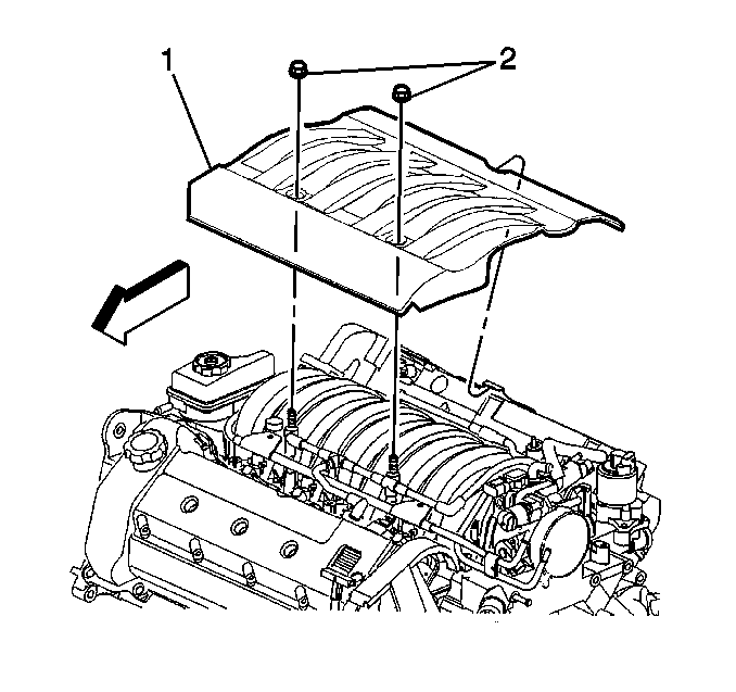
- Install the fuel injector
sight shield (1) to the engine.
Notice: Use the correct fastener in the correct location. Replacement fasteners
must be the correct part number for that application. Fasteners requiring
replacement or fasteners requiring the use of thread locking compound or sealant
are identified in the service procedure. Do not use paints, lubricants, or
corrosion inhibitors on fasteners or fastener joint surfaces unless specified.
These coatings affect fastener torque and joint clamping force and may damage
the fastener. Use the correct tightening sequence and specifications when
installing fasteners in order to avoid damage to parts and systems.
- Install the fuel
injector sight shield nuts (2).
Tighten
Tighten the nuts to 3 N·m (27 lb in).
- Install the rear seat cushion. Refer to
Rear Seat Cushion Replacement
in Seats.
