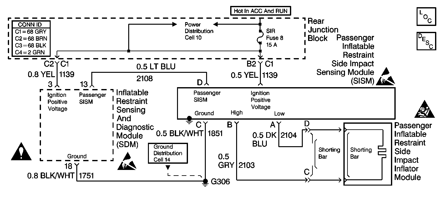
Circuit Description
When you turn the ignition switch to the ON position, the inflatable restraint side impact sensing module (SISM) performs tests to diagnose critical malfunctions within itself. The SISM then tests for the following conditions:
| • | Deployment loop open |
| • | Deployment loop short to ground |
| • | Deployment loop short to ignition |
| • | Deployment loop resistance high |
| • | Deployment loop resistance low |
| • | Deployment reserve energy failure |
The inflatable restraint side impact sensing module (SISM) transmits a pulse width modulated signal to the inflatable restraint sensing and diagnostic module (SDM) over CKT 2108. A 300 millisecond pulse width with a 50 percent duty cycle is the Normal mode and indicates that the SISM is operating normally and no faults exist. The SISM communicates that it is turning OFF (ignition OFF) by sending a 20 millisecond pulse width modulated signal with a 50 percent duty cycle.
Conditions for Setting the DTC
The SDM receives a pulse width signal other than the Normal signal, or no signal at all. The SISM performs tests during Power-On tests, Continuous Monitoring tests, and Asynchronously.
Action Taken When the DTC Sets
| • | The SDM sets DTC B1148. |
| • | The SDM commands the instrument cluster (IPC) to turn ON the AIR BAG warning lamp. |
Conditions for Clearing the DTC
| • | Current DTC: |
| - | The SDM receives a Normal signal from the SISM. |
| - | The ignition switch is cycled. |
| • | History DTC: |
| - | You issue a scan tool Clear DTCs command. |
| - | 250 malfunction-free ignition cycles occur. |
If a side impact deployment occurs the SISM must be replaced. Follow the instructions in the diagnostic table.
Diagnostic Aids
A poor connection can cause an intermittent condition. Check the following for a poor connection:
| • | The SISM. |
| • | The inflatable restraint side impact inflator module. |
| • | The SDM terminal 14. |
| • | The wire to terminal connections of all circuits going to the SISM. |
When measurements are requested in this table, use J 39200 Digital Multimeter with the correct terminal adapter from J 35616 Connector Test Adapter Kit. When a check for proper connection is requested, refer to General Electrical Diagnosis Procedures in Wiring Systems. When a wire, connector or terminal repair is requested, use J-38125 Terminal Repair Kit and refer to Wiring Repair .
Test Description
The numbers below refer to step numbers on the diagnostic table.
-
If the driver inflatable restraint side impact inflator deployed, DTC B1148 will set.
-
Components require inspection and possibly replacement after a side impact accident, whether deployment occurred or not.
-
This test determines if the malfunction is in the inflatable restraint side impact inflator module.
-
This test isolates the malfunction to the jumper harness or the pretensioner.
-
This test checks for an open in CKT 1851.
-
This test checks for an open in CKT 1139.
-
This test checks for a short to ground in CKT 2104.
-
This test checks for an open in CKT 2104.
-
This test checks for a short to voltage in CKT 2104.
-
This test checks for a short to ground in CKT 2103.
-
This test checks for a short to voltage in CKT 2103.
-
This test checks for high resistance or open in CKT 2103.
-
This test checks for a short to ground in CKT 2108.
-
This test checks for a short to voltage in CKT 2108.
-
This test checks for an open in CKT 2108.
-
If all wiring and connections are OK, then and only then should the inflatable restraint side impact sensing module (SISM) be replaced.
Important: If DTC B1327 is also set, repair low voltage malfunction first. Low voltage may erroneously set DTC B1148.
Step | Action | Value(s) | Yes | No |
|---|---|---|---|---|
1 | Was the SIR Diagnostic System Check performed? | -- | ||
Turn the ignition switch to the OFF position. Has the passenger inflatable restraint side impact inflator deployed? | -- | |||
Inspect the passenger side of the vehicle and the undercarriage for signs of a side impact. Are there signs of a side impact? | -- | |||
4 | Replace the components and perform the inspections as directed Repairs and Inspections Required After a Collision in this section. Have the appropriate repairs and inspections been completed? | -- | -- | |
Is DTC B1148 current? | -- | |||
Is DTC B1148 current? | -- | |||
7 |
Have the repairs been completed? | -- | -- | |
8 |
Has the inflatable restraint side impact inflator module been replaced? | -- | -- | |
9 |
Are any of the SISM harness connector terminals damaged or corroded? | -- | ||
10 | Replace the SISM harness connector. Refer to Wiring Repair . Have the repairs been completed? | -- | -- | |
11 | Carefully inspect the SISM connector terminals for damage or corrosion. Are any of the SISM connector terminals damaged or corroded? | -- | ||
12 | Replace the SISM harness connector. Refer to Driver and Passenger Seat Side Inflatable Restraint Module Replacement . Has the SISM been replaced? | -- | -- | |
Using J 39200 DMM, measure the resistance from the SISM harness connector C to ground. Is the resistance within the specified values? | 0-0.5 ohms | |||
14 | Repair an open condition in CKT 1851. Refer to Wiring Repair . Have the repairs been completed? | -- | -- | |
Using J 39200 DMM, measure the resistance from the SISM terminal E to each terminal of the SIR Fuse fuseholder. Is the resistance within the specified values? | 0-0.5 ohms | |||
16 | Repair an open condition in CKT 1139. Refer to Wiring Repair . Have the repairs been completed? | -- | -- | |
Is the resistance within the specified values? | 0-0.5 ohms | |||
18 | Repair a short to ground condition in CKT 2104. Refer to Wiring Repair . Have the repairs been completed? | -- | -- | |
Using J 39200 DMM, measure the resistance from the SISM terminal A to the inflatable restraint side impact inflator module terminal D. Is the resistance within the specified values? | 0-0.5 ohms | |||
20 | Repair a high resistance condition in CKT 2104. Refer to Wiring Repair . Have the repairs been completed? | -- | -- | |
Is the voltage more than the specified value? | 1 V | |||
22 | Repair short to voltage condition in CKT 2104. Refer to Wiring Repair . Have the repairs been completed? | -- | -- | |
Using J 39200 DMM, measure the voltage from the SISM harness connector terminal B to ground. Is the voltage more than the specified value? | 1 V | |||
24 | Repair a short to voltage condition in CKT 2103. Refer to Wiring Repair . Have the repairs been completed? | -- | -- | |
Using J 39200 DMM, measure the resistance from the SISM harness connector terminal B to ground. Is the resistance within the specified values? | 0-0.5 ohms | |||
26 | Repair a short to ground condition in CKT 2103. Refer to Wiring Repair . Have the repairs been completed? | -- | -- | |
Using J 39200 DMM, measure the resistance from the SISM harness connector terminal B to the inflatable restraint side impact inflator module harness connector terminal C. Is the resistance within the specified values? | 0-0.5 ohms | |||
28 | Repair a high resistance or open condition in CKT 2103. Refer to Wiring Repair . Have the repairs been completed? | -- | -- | |
Using J 39200 DMM, measure the resistance from the SISM harness connector terminal D to ground. Is the resistance within the specified value? | 0-0.5 ohms | |||
30 | Repair a short to ground condition in CKT 2108. Refer to Wiring Repair . Have the repairs been completed? | -- | -- | |
Is the voltage more than the specified value? | 1 V | |||
32 | Repair a short to voltage condition in CKT 2108. Refer to Wiring Repair . Have the repairs been completed? | -- | -- | |
33 |
Is terminal 14 of the SDM harness connector damaged or corroded? | -- | ||
34 | Replace the SDM harness connector. Refer to Wiring Repair . Have the repairs been completed? | -- | -- | |
35 | Carefully inspect SDM connector terminal 14 for damage or corrosion. Is terminal 14 of the SDM connector damaged or corroded? | |||
36 | Replace the SDM. Refer to Inflatable Restraint Sensing and Diagnostic Module Replacement . Has the SDM been replaced? | -- | -- | |
Using J 39200 DMM, measure the resistance from the SDM harness connector terminal 14 to the SISM harness connector terminal D. Is the resistance within the specified values? | 0-0.5 ohms | |||
38 | Repair a high resistance or open condition in CKT 2108. Refer to Wiring Repair . Have the repairs been completed? | -- | -- | |
Replace the passenger SISM. Refer to Inflatable Restraint Side Impact Sensing and Diagnostic Module Replacement - Right Side . Has the SISM been replaced? | -- | -- | ||
40 |
Is DTC B1147 current? | -- | ||
41 | Reconnect all the SIR System components. Make sure all the components are properly mounted. Have all the SIR System components been properly mounted? | -- | -- |
