Circuit Description
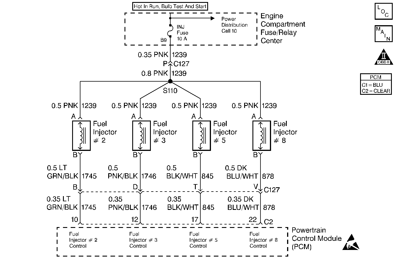
This PCM contains a General F.E.T. (Field Effect Transistor) Driver (GFD) that controls the eight fuel injector drivers. The GFD contains circuitry that is used to determine if there is a problem with any of the fuel injector circuits. The GFD has a fault line for each injector. The fault line goes high when an open, short to ground, or short to voltage is noticed in an injector circuit. DTC P0205 is set when the fault line for injector #5 is high.
Conditions for Setting the DTC
Test Conditions
| • | DTCs P0560 and P1376 not set. |
| • | Ignition voltage between 10 and 16 volts. |
Failure Condition
An injector circuit fault is detected for 0.5 second.
Action Taken When the DTC Sets
| • | The faulty injector is disabled for the engine run cycle. |
| • | PCM disables Closed Loop operation. |
| • | The PCM will illuminate the malfunction indicator lamp (MIL) when the diagnostic runs and fails. |
| • | The PCM will record operating conditions at the time the diagnostic fails. This information will be stored in the Freeze Frame and Failure Records. |
Conditions for Clearing the MIL/DTC
| • | The PCM will turn the MIL OFF after three consecutive drive trips that the diagnostic runs and does not fail. |
| • | A Last Test Failed (current) DTC will clear when the diagnostic runs and does not fail. |
| • | A History DTC will clear after forty consecutive warm-up cycles with no failures of any emission related diagnostic test. |
| • | Use a scan tool to clear DTCs. |
| • | Interrupting PCM battery voltage may or may not clear DTCs. This practice is not recommended. Refer to Clearing Diagnostic Trouble Codes in PCM Description and Operation. |
Test Description
Number(s) below refer to the step number(s) on the Diagnostic Table.
-
If DTCs P0202, P0203 and P0208 are also set, power must be disabled to injectors 2, 3, 5 and 8.
-
If DTC P0205 is not current, drive vehicle until DTC resets. This will bring the injectors to the temperature at which the DTC set.
-
Checking to see if injector #5 is receiving voltage. If not, the fault must be in the injector 2, 3, 5, 8 ignition feed circuit between the splice and injector #5.
-
Checking for a shorted injector. Resistance should be between 8 to 25 ohms.
-
Checking for poor terminal contact at PCM connector C2 terminal 17.
-
Checking for an open or short to ground in the injector 5 control circuit between PCM and fuel rail connector.
-
Checking for a short to ground in the injector 5 control circuit between fuel rail connector and injector #5.
-
Checking for an open fuel injector. Resistance should be between 8 to 25 ohms.
Step | Action | Value(s) | Yes | No |
|---|---|---|---|---|
1 | Was the Powertrain On-Board Diagnostic (OBD) System Check performed? | -- | Go to A Powertrain On Board Diagnostic (OBD) System Check | |
Are DTCs P0202, P0203 and P0208 also set? | -- | Go to DTC P0202 Injector 2 Control Circuit (Engine Oil Level Low Message) | ||
On the scan tool select Last Tst. Fail. Has this DTC failed its last test? | -- | |||
4 | Clear DTCs, operate vehicle until DTC P0205 resets. Does DTC P0205 reset? | -- | Fault not present | |
Is voltage the same or higher than the value specified? | 10 volts | |||
6 |
Is voltage more than the value specified? | 10 volts | ||
Is resistance more than the value specified? | 8 ohms | |||
8 | Measure voltage to ground at injector #5 connector terminal B (harness side). Is voltage the same or lower than the value specified? | 0.1 volt | ||
Was terminal contact repaired? | -- | Go to Powertrain Control Module Diagnosis for Verify Repair | ||
Is voltage lower than the value specified? | 10 volts | |||
Is resistance more than the value specified? | 10K ohms | |||
Measure resistance between injector #5 pins A and B. Is resistance more than the value specified? | 25 ohms | |||
13 | Repair open in the injector 2, 3, 5, 8 ignition feed circuit between splice and fuel injector #5. Is the repair complete? | -- | Go to Powertrain Control Module Diagnosis for Verify Repair | -- |
14 | Repair short to voltage on the injector 5 control circuit. Is the repair complete? | -- | Go to Powertrain Control Module Diagnosis for Verify Repair | -- |
15 | Repair open or short to ground in the injector 5 control circuit between fuel rail connector and injector #5. Is the repair complete? | -- | Go to Powertrain Control Module Diagnosis for Verify Repair | -- |
16 | Repair short to ground in the injector 5 control circuit between fuel rail connector and injector #5. Is the repair complete? | -- | Go to Powertrain Control Module Diagnosis for Verify Repair | -- |
17 | Repair open in the injector 5 control circuit between fuel rail connector and injector #5. Is the repair complete? | -- | Go to Powertrain Control Module Diagnosis for Verify Repair | -- |
18 | Replace the fuel injector. Refer to Fuel Injector Replacement . Is the replacement complete? | -- | Go to Powertrain Control Module Diagnosis for Verify Repair | -- |
19 | Replace the PCM. Refer to PCM Replacement/Programming . Is the replacement complete? | -- | Go to Powertrain Control Module Diagnosis for Verify Repair | -- |
