INTERMITTENT RICH OPERATION ERRATIC TCC OPER. CODES 15/38

MODELS AFFECTED: 1980 ELDORADOS AND SEVILLES WITH 6.0L DEFI ENGINE 1981 FLEETWOOD BROUGHAMS, DE VILLES, ELDORADOS AND SEVILLES WITH 6.0L DFI ENGINE 1981-84 LIMOUSINE WITH 6.0L DFI ENGINE 1982-1985 FLEETWOOD BROUGHAMS, DE VILLES, ELDORADOS AND SEVILLES WITH HT4100 DFI ENGINE 1983-1984 CIMARRONS 1985 FWD FLEETWOODS AND DE VILLES WITH HT4100 DFI ENGINE 1985 FWD LIMOUSINE WITH 4.1L DFI ENGINE
This bulletin supersedes 85-108, Group 6E, which should be destroyed.
Some 1980-1985 vehicles with fuel injection may experience intermittent rich operation, black smoke during restarts, erratic Torque Converter Clutch engagement and disengagement, and/or ECM diagnostic codes 15 or 38. These conditions can result from an open circuit or excessive resistance in the Manifold Air Temperature (MAT) and/or coolant sensor circuits. These conditions can be diagnosed by using diagnostic engine data display parameters P.O.4 and P.O.5. Display parameter P.O.4 (coolant temperature) and observe the parameter while an assistant moves or manipulates the coolant sensor wire harness connector. An open circuit condition will cause the coolant temperature to read an unrealistically low temperature (i.e., 0 deg. C, -38 deg. C etc.). Repeat this procedure with parameter P.O.5 (MAT). An open circuit in the MAT circuit will also result in an unrealistically low temperature reading. The coolant temperature should not vary rapidly under steady throttle conditions.
To correct the above conditions, it is necessary to replace either the MAT sensor and MAT connector or the coolant sensor and coolant connector with Metri-Pack type connectors.
The following part numbers are required to equip a vehicle with the new Metri-Pack connectors.
PART NAME PART NUMBER --------- ----------- Coolant Sensor 25036708 Coolant Sensor Wire Harness Kit 12046623 MAT Sensor 25036751 MAT Sensor Wire Harness Kit 12046624
To replace the MAT and coolant wire harness connectors, refer to the attached instructions on wire splicing and soldering.
IMPORTANT: The MAT and coolant wire harness connector wires must be spliced and soldered. Do not use solderless lock type connectors to secure the wires.
Coolant and MAT sensors with the old style connectors are still available from GMWDD. It is important to specify Metri-Pack type connectors if an intermittent problem is suspected.
SPLICING INSTRUCTIONS FOR MANIFOLD AIR TEMPERATURE (MAT) OR COOLANT TEMPERATURE METRI-PACK WIRE HARNESS CONNECTOR SERVICE KIT
The Manifold Air Temperature (MAT) or Coolant Temperature sensor must be replaced when a MAT or coolant wire hamess connector service kit is installed on a vehicle which does not have a Metri-Pack (flat connector pin) MAT or Coolant sensor. The sensors should be ordered using the following part numbers:
MAT Sensor 25036751 Coolant Sensor 25036708
IMPORTANT: Due to the very low currents in the MAT and coolant circuits, it is very important to solder the wire splice joints to ensure good electric conductivity.
Step One: Open the Harness -------------------------- If the harness is taped, remove the tape. To avoid wire insulation damage, use a sewing "seam ripper" to cut open the harness (available from sewing supply stores).
If the harness has a plastic conduit, simply pull out the desired wire.
Step Two: Cut the Wire ---------------------- With the wires pulled out of the plastic conduit, cut the first wire at least three inches into the conduit to ensure that the splice will be protected by the conduit. Cut the second wire 1 1/2 inches further into the conduit, or 4 1/2 inches from the end of the conduit.
Step Three: Strip the Insulation -------------------------------- If you aren't sure of the wire size, start with the largest opening in your wire stripper and work down until you get a clean strip of the insulation. Be careful to avoid nicking or cutting any of the wires.
Check the stripped wire for nicks or cut strands. If the wire is damaged, repeat the procedure on a new section of wire. The two stripped wire ends should be equal in length.
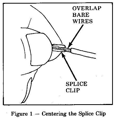
Step Four: Crimp the Wires -------------------------- Locate the clip contained in the service kit. Select the correct anvil on the crimper. (On most crimpers your choice is limited to either a small or large anvil.) Overlap the two stripped wire ends and hold them between your thumb and forefinger as shown (see Figure 1). Then, center the splice clip under the stripped wires and hold it in place.
- Open the crimping tool to its full width and rest one handle on a firm flat surface.
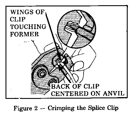
- Center the back of the splice clip on the proper anvil and close the crimping tool to the point where the former touches the wings of the clip.
- Make sure that the clip and wires are still in the correct position. Then, apply steady pressure until the crimping tool closes (see Figure 2).
Before crimping the ends of the clip, be sure that
- The wires extend beyond the clip in each direction, - No strands of wire are cut loose, and - No insulation is caught under the clip.
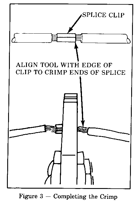
Crimp the splice clip again, once on each end. Do not let the crimping tool extend beyond the edge of the clip or you may damage or nick the wire (see Figure 3).
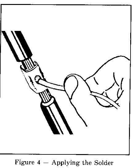
Step Five: Solder ----------------- Apply 50/50 rosin core solder to the opening in the back of the clip as shown (see Figure 4). Follow the manufacturer's instructions for the solder equipment you are using.
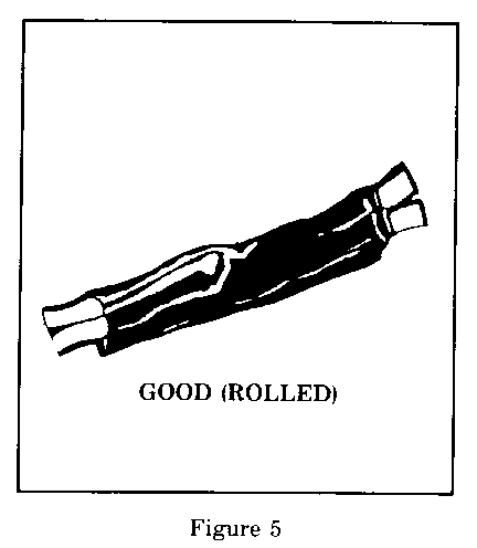
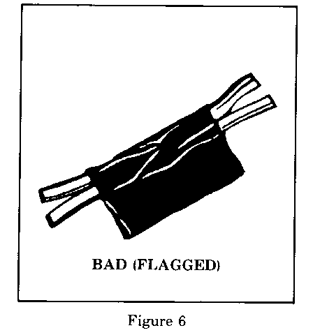
Step Six: Tape the Splice ------------------------- Center and roll the splicing tape. The tape should cover the entire splice. Roll on enough tape to duplicate the thickness of the insulation on the existing wires (see Figure 5). Do not flag the tape. Flagged tape may not provide enough insulation, and the flagged ends will tangle with the other wires in the harness (see Figure 6).
Step Seven: Reinstall Wire in Conduit or Retape Harness --------------------------------------------------------
For warranty purposes use the following labor operations and times when installing Metri-Pack type sensors and connectors:
T6127 - Replace Coolant Sensor and Coolant Connector 80 E/K - .7 hr. 81 C/E/K - 1.2 hr. 82-83C, 84-85D - .5 hr. 82-85 E/K - .5 hr. 83-84 J - .7 hr. 85C - .6 hr.
T6129 - Replace MAT Sensor and MAT Connector 80-85 E/K - .5 hr. 81-83C, 84-85D - .5 hr. 85C - .6 hr.
General Motors bulletins are intended for use by professional technicians, not a "do-it-yourselfer". They are written to inform those technicians of conditions that may occur on some vehicles, or to provide information that could assist in the proper service of a vehicle. Properly trained technicians have the equipment, tools, safety instructions and know-how to do a job properly and safely. If a condition is described, do not assume that the bulletin applies to your vehicle, or that your vehicle will have that condition. See a General Motors dealer servicing your brand of General Motors vehicle for information on whether your vehicle may benefit from the information.
