For 1990-2009 cars only
Special Tools
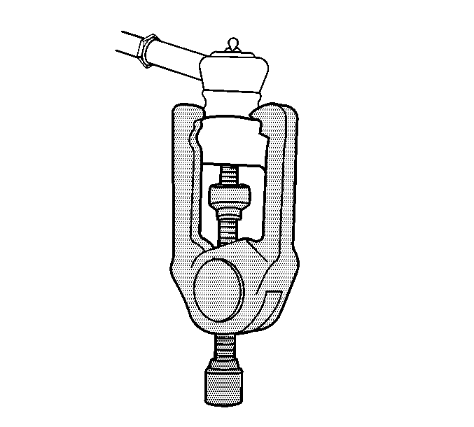
| • | J 24319-B Steering Linkage and Tie Rod Puller |
| • | J 42640 Steering Column Anti-Rotation Pin |
Removal Procedure
- Install the J 42640 Pin in order to lock the steering column in the straight ahead position.
- Raise and support the vehicle. Refer to Lifting and Jacking the Vehicle.
- Remove the front tire and wheel assemblies. Refer to Tire and Wheel Removal and Installation.
- If necessary in order to access the steering gear, remove the front air deflector. Refer to Front Air Deflector Replacement.
- Remove the left side engine splash shield. Refer to Engine Splash Shield Replacement.
- Remove the intermediate shaft lower pinch bolt.
- Disconnect the intermediate shaft from the power steering gear.
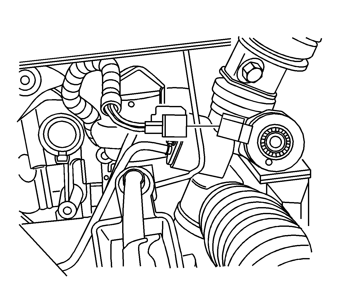
- Disconnect the variable effort steering harness connector.
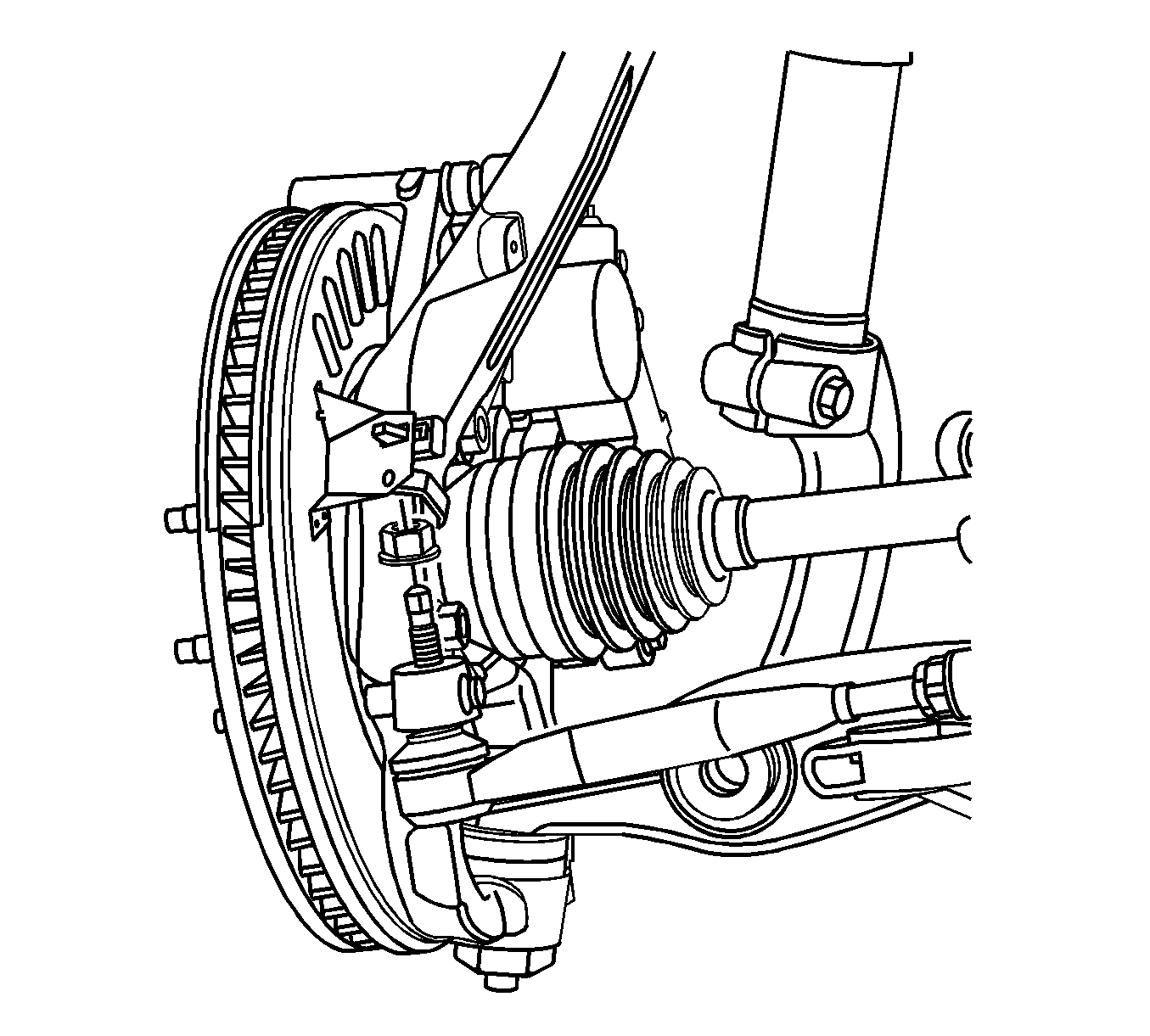
- Remove the outer tie rod retaining nuts.
- Using the J 24319-B Puller , separate the outer tie rod from the steering knuckles.
- Place a drain pan under the vehicle.
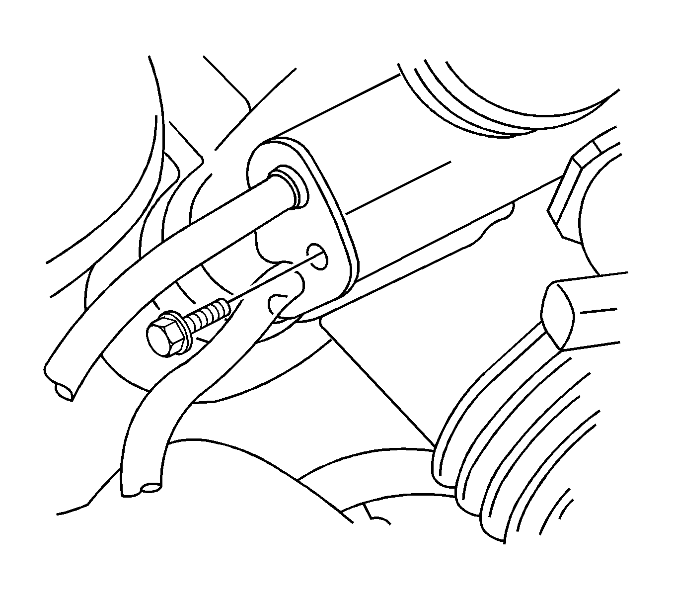
- Remove the power steering hoses to power steering gear retaining bolt.
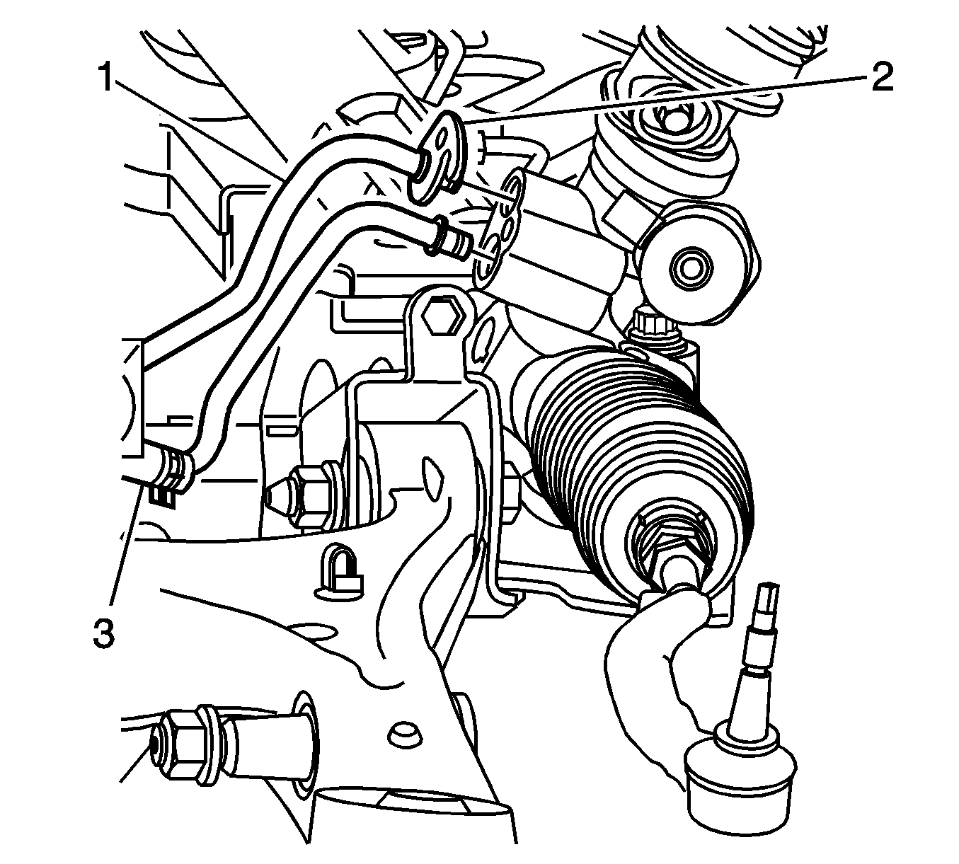
- Remove the power steering hoses (1, 3) from the power steering gear.
- If equipped with AWD, perform the following steps:
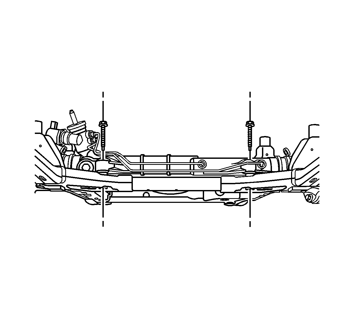
- Remove the power steering gear mounting bolts.
- If equipped with the 4.6L V8 (LH2) engine and all wheel drive (AWD), perform the following steps:
- Remove the power steering gear through the left wheel opening.
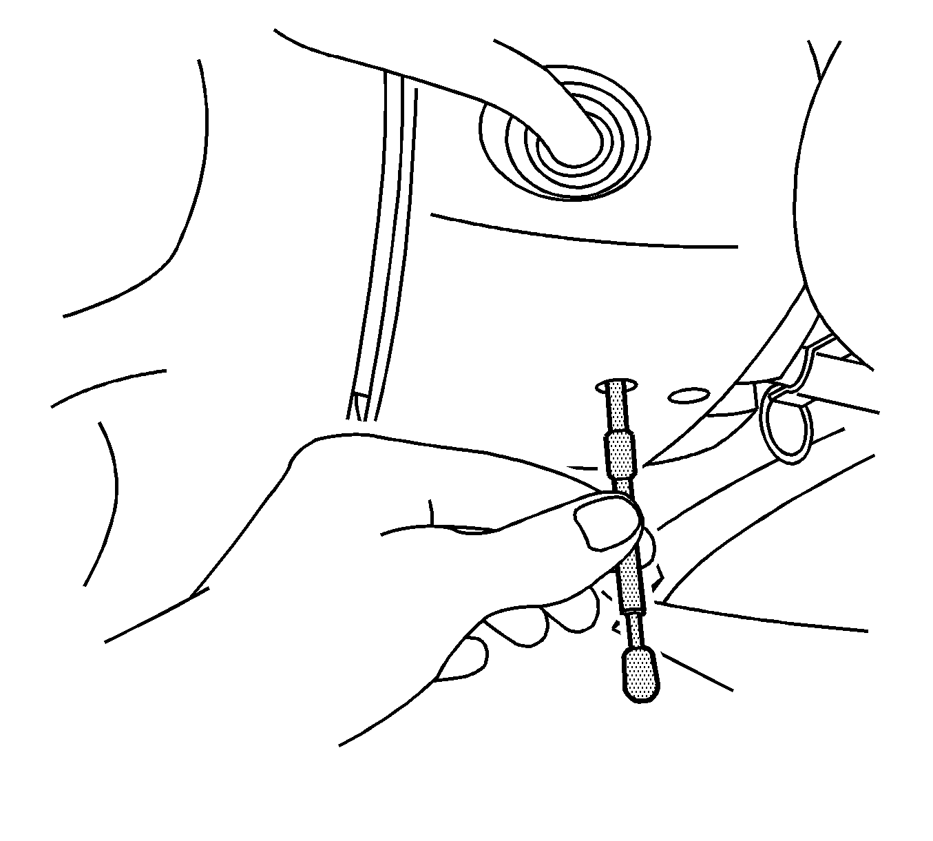
Caution: The wheels of the vehicle must be straight ahead and the steering column in the LOCK position before disconnecting the steering column or intermediate shaft from the steering gear. Failure to do so will cause the coil assembly in the steering column to become uncentered which will cause damage to the coil assembly.
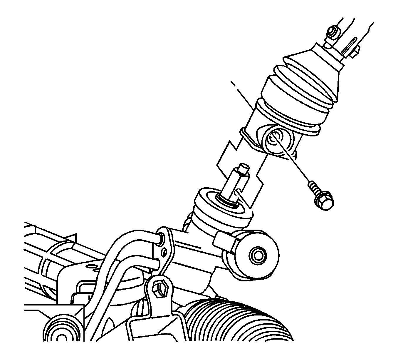
Warning: Failure to disconnect the intermediate shaft from the rack and pinion steering gear stub shaft can result in damage to the steering gear and/or intermediate shaft. This damage may cause loss of steering control which could result in an accident and possible personal injury.
| 14.1. | Use a suitable jack in order to support the bottom of the front differential housing. |
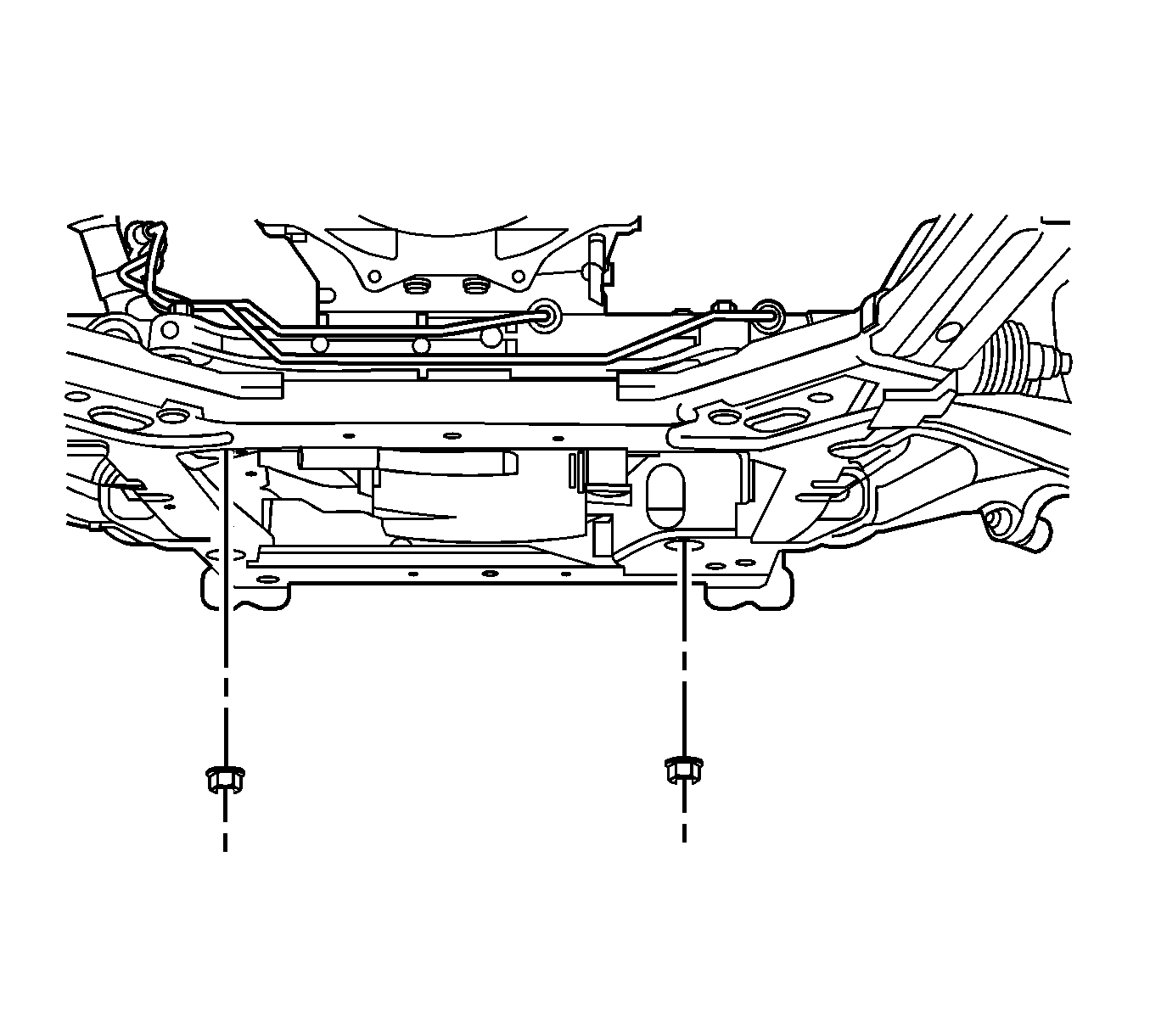
| 14.2. | Loosen the right engine mount nut. |
| 14.3. | Raise the differential housing in order to clear the steering rack bolt. |
| 16.1. | Disconnect the left brake pipe from the brake hose. |
| 16.2. | Plug the brake pipe. |
| 16.3. | Carefully position the brake pipe to the side. |
| 16.4. | Remove the nut and the bolt that retain the rear of the left front lower control arm to the frame. |
Installation Procedure
- Install the power steering gear through the left wheel opening.
- If equipped with the LH2 engine and AWD, perform the following steps:
- Install the power steering gear retaining bolts and tighten to 180 N·m (133 lb ft).
- If equipped with AWD, perform the following steps:
- Install the power steering hoses (1, 3) to the power steering gear.
- Install the power steering hoses to power steering gear retaining bolt and tighten to 23 N·m(17 lb ft).
- Remove the drain pan from under the vehicle.
- Install the outer tie rod to the steering knuckles and tighten the nuts to 70 N·m (52 lb ft).
- Connect the variable effort steering harness connector.
- Connect the intermediate shaft to the power steering gear.
- Install the intermediate shaft lower pinch bolt and tighten to 50 N·m (37 lb ft).
- Install the left side engine splash shield. Refer to Engine Splash Shield Replacement.
- Install the tire and wheel assemblies. Refer to Tire and Wheel Removal and Installation.
- If you removed the front air deflector, install the front air deflector. Refer to Front Air Deflector Replacement.
- Lower the vehicle.
- Remove the J 42640 Pin from the steering column.
- Bleed the power steering system. Refer to Power Steering System Bleeding.
- Adjust the front toe. Refer to Wheel Alignment - Steering Wheel Angle and/or Front Toe Adjustment.
Caution: Refer to Fastener Caution in the Preface section.
| 2.1. | Install the left brake pipe to the brake hose and tighten to 27 N·m (20 lb ft). |
| 2.2. | Install the bolt in order to retain the rear of the left front lower control arm to the frame. |
| Note: Tighten the lower control arm nut with the lower control arm at normal vehicle ride height. |
| 2.3. | Install the lower control arm nut to the bolt and tighten to 135 N·m (96 lb ft). |

| 4.1. | Lower the differential housing. |

| 4.2. | Install the right lower engine mount to frame nut and tighten to 80 N·m (59 lb ft). |
| 4.3. | Remove the support from the bottom of the differential housing. |


