For 1990-2009 cars only
Tools Required
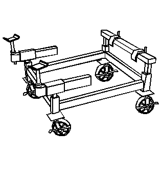
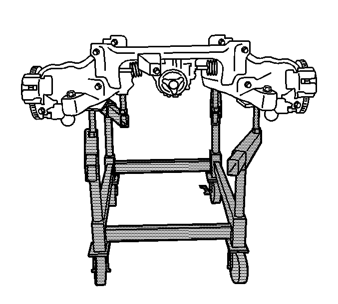
J 39580 Engine Support Stand
Removal Procedure
- Raise and support the vehicle. Refer to Lifting and Jacking the Vehicle .
- Remove the rear suspension bracket. Refer to Rear Suspension Bracket Replacement .
- Remove the rear wheels. Refer to Tire and Wheel Removal and Installation .
- Remove the exhaust system. Refer to Exhaust System Replacement .
- Remove the driveshaft from the differential. Refer to Rear Propeller Shaft Replacement .
- Install the support fixture (3), in order to raise the lower control arm to relieve the tension from the shock.
- Remove the shocks lower mounting bolt (2).
- Remove the support fixture.
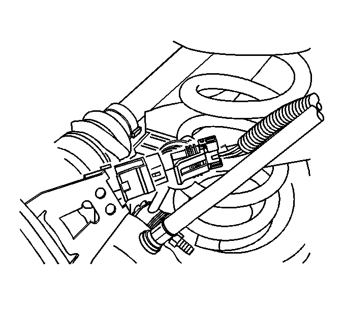
- Disconnect the electrical connectors for the rear wheel speed sensors (WSSs).
- Disconnect the retainer clips on the park brake cables for the WSSs wiring harness.
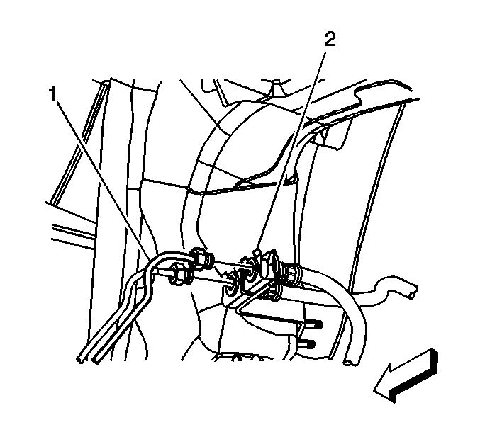
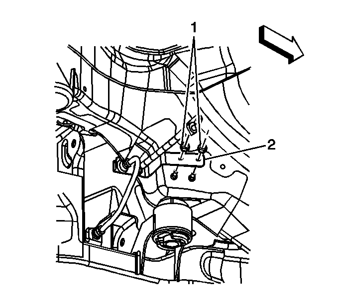
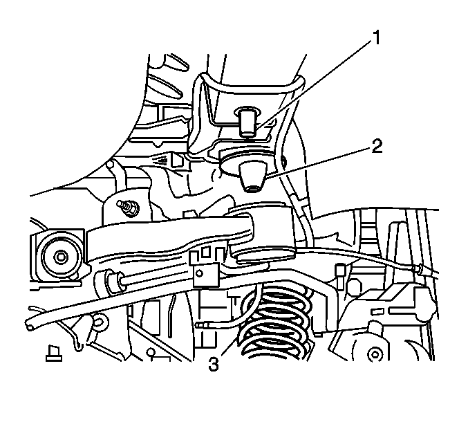
- Disconnect the rear brake pipe lines (1) forward of the rear wheelhouse.
- Remove the fastener for the brake pipe bracket (1).
- Remove the brake pipe bracket (2) from the studs in the body.
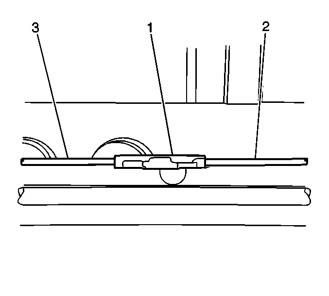
- Disconnect the intermediate park brake cable (2) from the front park brake cable connector.
- Disconnect the intermediate park brake cable (2) from the rear park brake cable connector (1).
- Position the frame support table J 39580 .
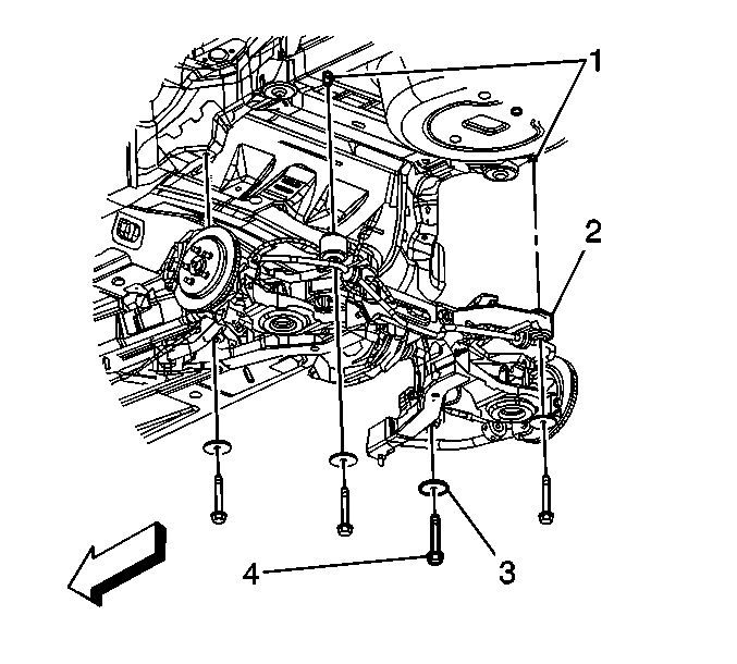
- Remove the frame to body mounting bolts (4) and washers (3).
- Carefully raise the vehicle from the rear frame assembly.
- Remove the following components from the rear frame:
- With the aid from an assistant, remove the frame from the hydraulic jack.
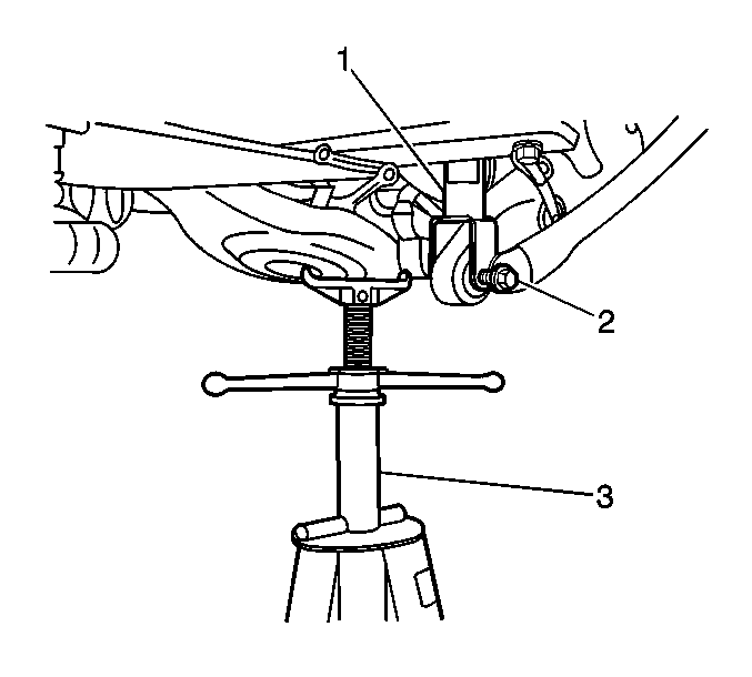
Important: The lower control arms will drop approximately 3 inches when the shock to lower control arm bolts are removed.
| • | The rear brake pipes |
| • | Parking Brake Rear Cable Replacement - Left Side or Parking Brake Rear Cable Replacement - Right Side |
Installation Procedure
- With the aid from an assistant, position and secure the new rear frame on the engine support fixture.
- Install the following components to the rear frame assembly:
- Index the rear coil springs to the spring insulators.
- Ensure the intermediate park brake cable is positioned over left side frame assembly on the left side.
- Lower the vehicle to the frame.
- Position the coil springs (3) to the upper spring insulator (2).
- Index the rear side frame mounts to the rear locator sleeves (1) located on the body.
- Lower the vehicle until the frame mounts contact the body rail.
- Install the rear frame washers (3) and anchor bolts (4).
- Raise the vehicle.
- Remove the J 39580 .
- Install the support fixture (3) in order to raise the lower control arms for ease of lower shock bolt installation (2).
- Install the lower shock bolt.
- Repeat the above step for the other side.
- Remove the support fixture (3).
- Connect the intermediate park brake cable (2) to the rear park brake cable connector (1).
- Connect the intermediate park brake cable (2) to the front park brake cable connector.
- Position the brake pipe bracket (2) to the body studs.
- Install the brake pipe bracket retaining nuts (1).
- Connect the rear brake lines (1) at the forward rear wheelhouse.
- Connect the rear WSS electrical connectors.
- Secure the electrical harness retainer clips to the park brake cables.
- Install the rear wheels. Refer to Tire and Wheel Removal and Installation .
- Install the rear suspension bracket. Refer to Rear Suspension Bracket Replacement .
- Lower the vehicle.
- Bleed the hydraulic brake system. Refer to Hydraulic Brake System Bleeding .
- Align the vehicle. Refer to Wheel Alignment Measurement .
| • | Parking Brake Rear Cable Replacement - Left Side or Parking Brake Rear Cable Replacement - Right Side |
| • | The rear brake pipes |
Important: The rear coil springs need to be indexed into the lower spring insulators prior to assembly.
Important: Ensure the intermediate brake cable is clear of the front frame to body mount prior to securing the frame bolts.
Notice: Refer to Fastener Notice in the Preface section.
Tighten
| • | Tighten the front bolts to 265 N·m (195 lb ft). |
| • | Tighten the rear bolts to 191 N·m (141 lb ft). |
Tighten
Tighten the bolt (2) to 150 N·m (111 lb ft).
Tighten
Tighten the nuts to 10 N·m (89 lb in).
Tighten
Tighten the lines to 15 N·m (11 lb ft).
