Removal Procedure
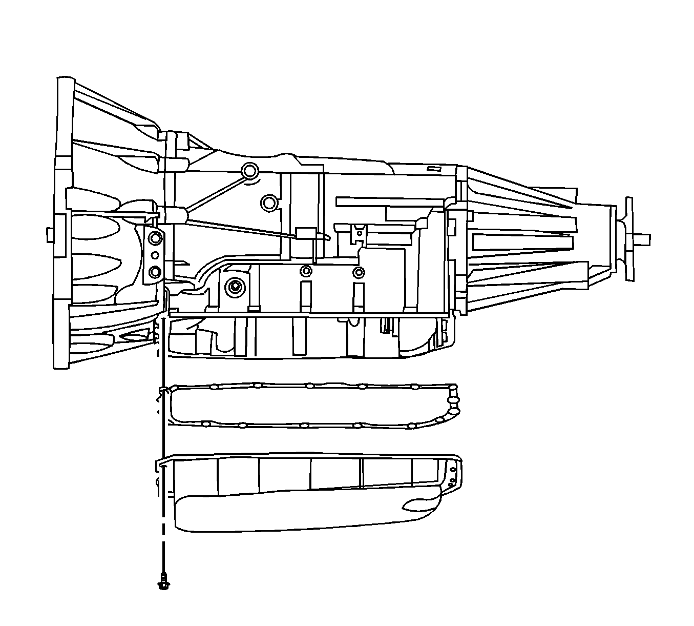
- Remove the transmission oil pan and filter. Refer to Automatic Transmission Fluid, Fluid Pan and/or Filter Replacement .
- Remove the electrical connector passage sleeve. Refer to Automatic Transmission Electrical Connector Passage Sleeve Replacement .
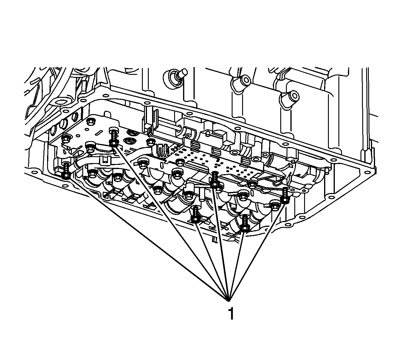
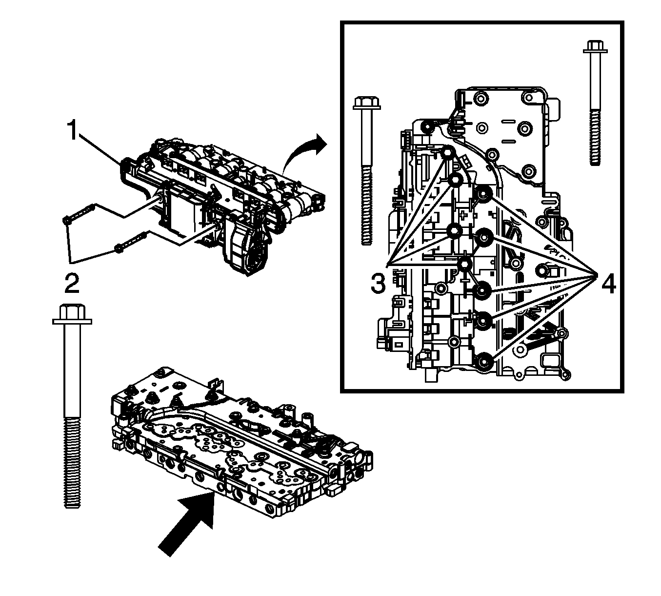
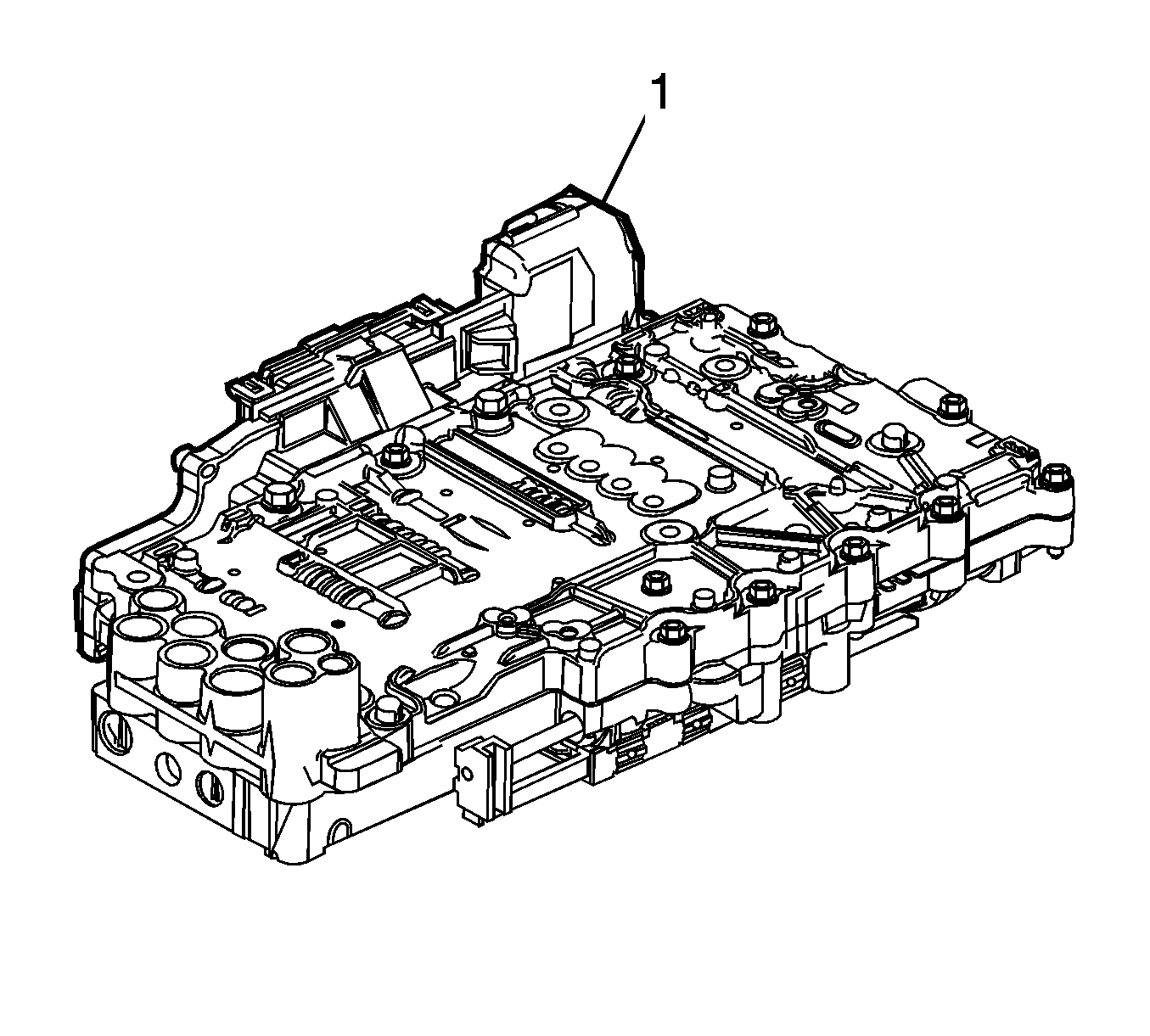
- Remove the valve body bolts (1).
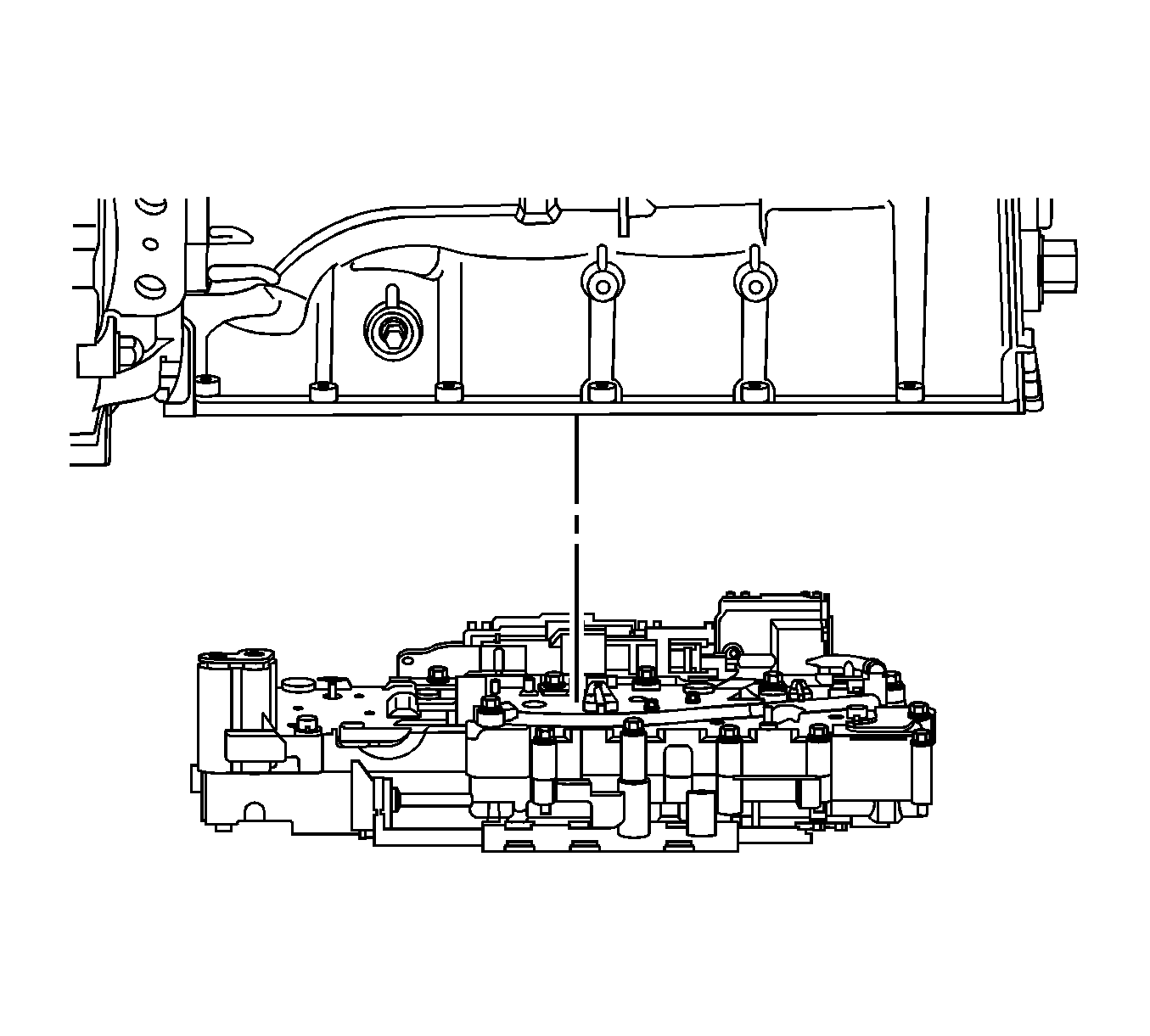
- Remove the upper and lower control valve body assembly.
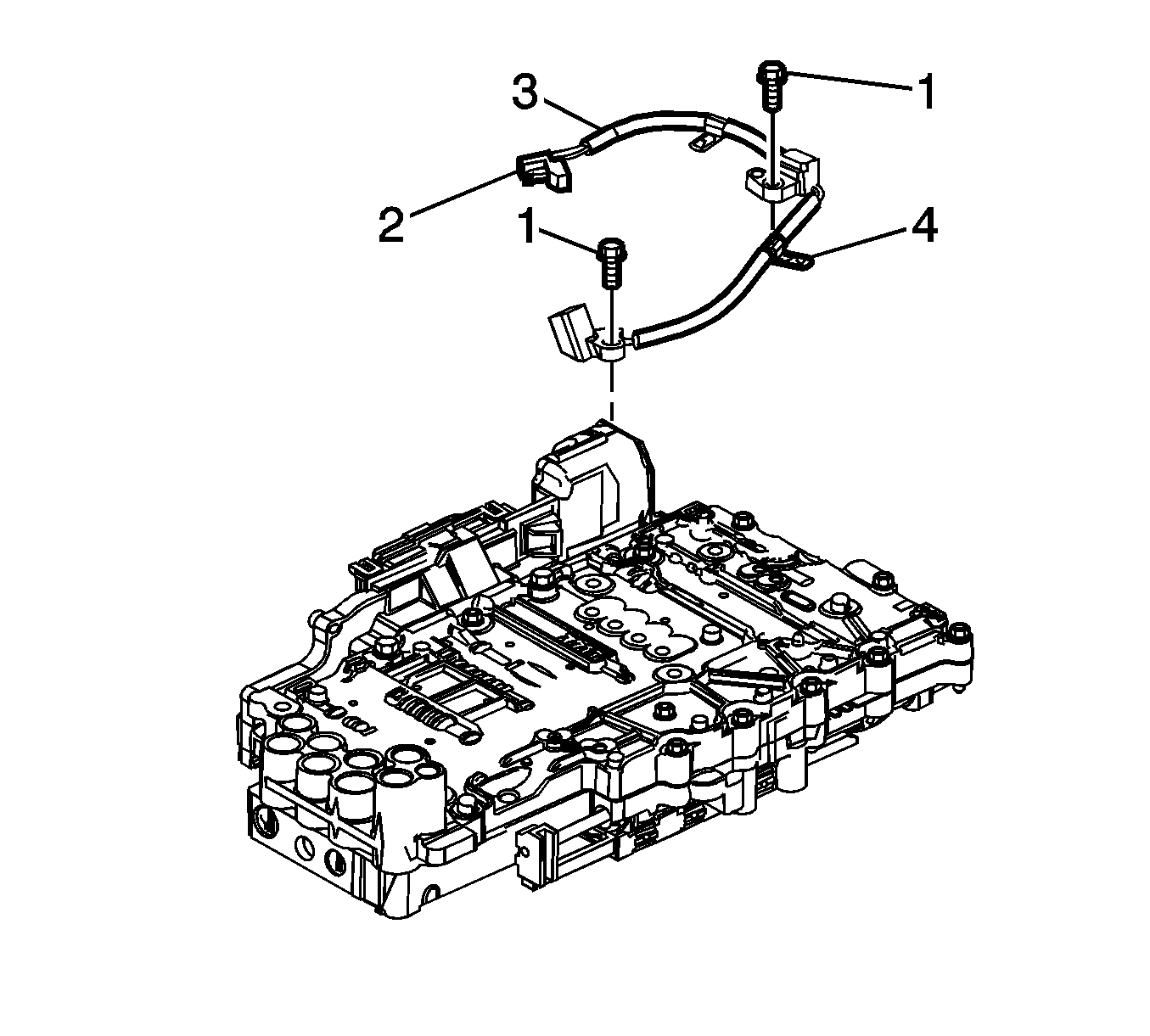
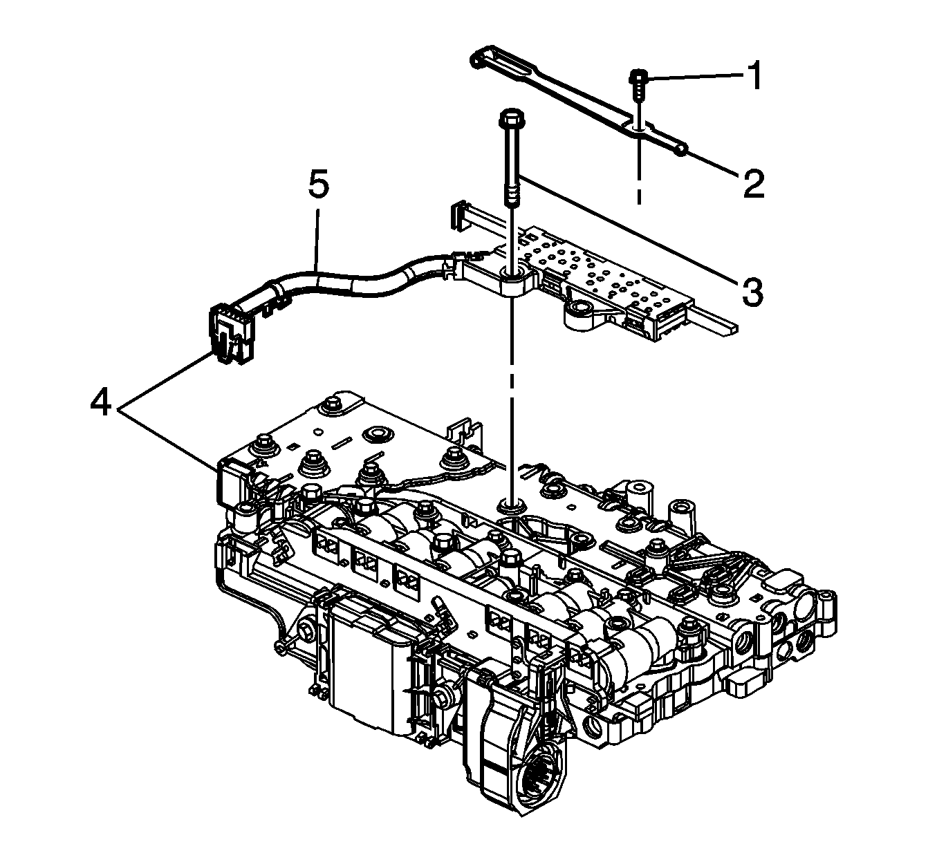
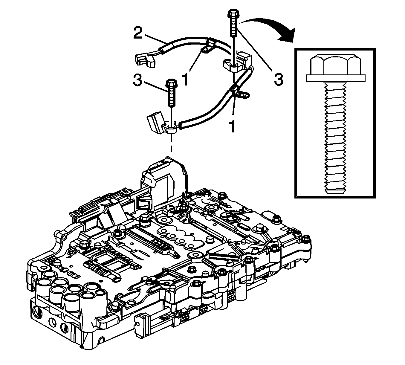
- Disconnect the speed sensor electrical connector (2) from the control solenoid valve assembly.
- Turn the control valve body assembly over.
- Disconnect the manual shift shaft position switch connector (4) from the control solenoid valve assembly.
- Remove the bolt (3) and remove the manual shift shaft position switch assembly.
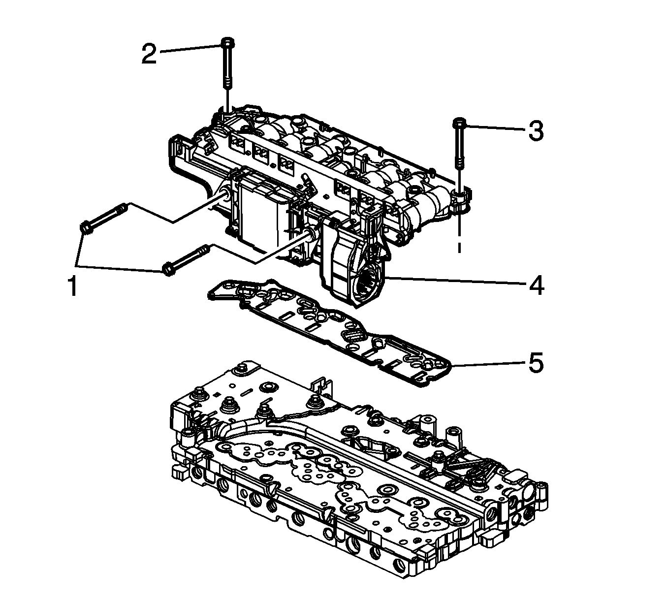
- Remove the 2 bolts (1) from the "heat sink" side of the control solenoid valve assembly.
- Remove the 5 bolts (2) and the 4 bolts (1) securing the control solenoid valve assembly to the control valve body assembly.
- Remove the control valve body assembly.
- Carefully remove and discard the filter plate assembly (5).
Important: The valve body must be removed from the transmission to replace the control solenoid valve and transmission control module assembly.
Important: Release the connector lock before disconnecting.
Notice: Use care when removing or installing the filter plate assembly. A broken or missing retaining tab may not adequately secure the filter plate to the control solenoid valve assembly, resulting in possible damage or contamination.
Installation Procedure
- Install a NEW filter plate assembly (1).
- Align the control solenoid valve assembly (1) to the control valve lower body assembly.
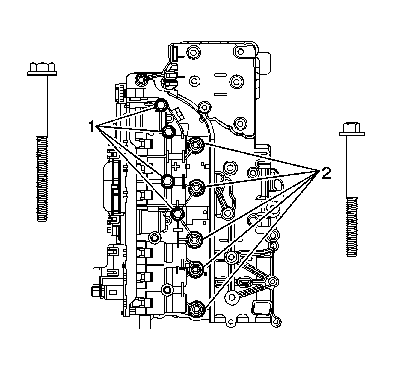
- Install the 2 bolts (2), through the "heat sink" side of the control solenoid valve assembly (1). Hand tighten only.
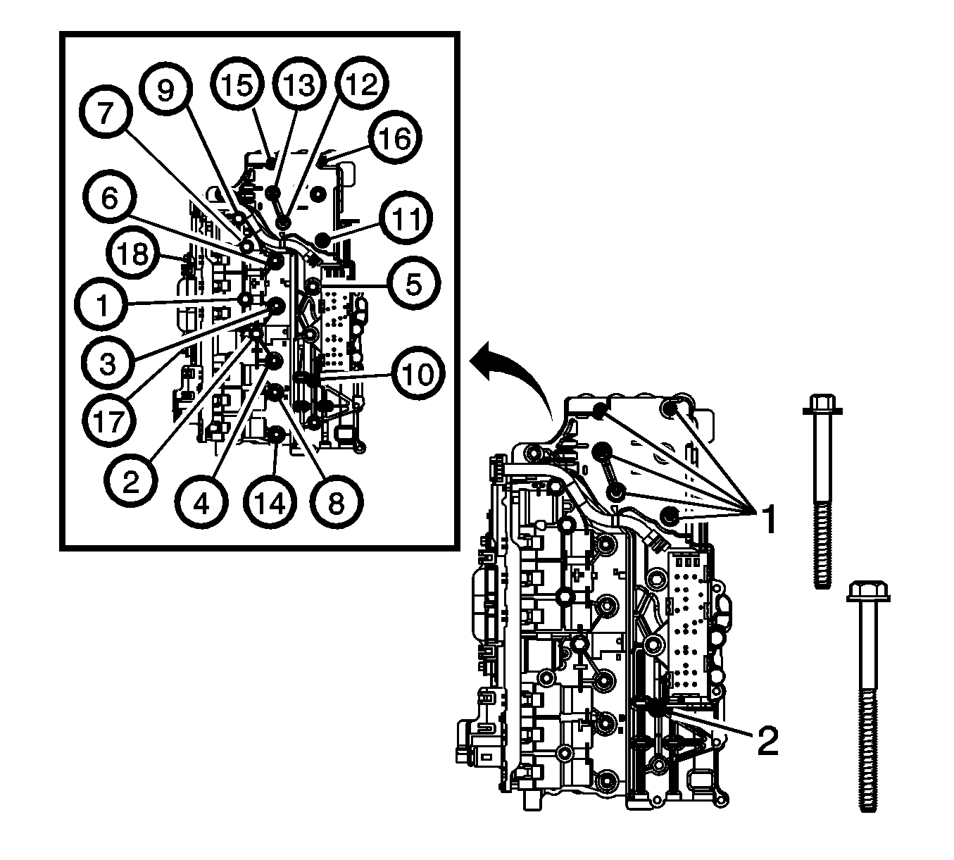
- Install the 4 bolts (1) and 5 bolts (2) securing the control solenoid valve assembly to the control valve lower body assembly. Hand tighten only.
- Install the manual shift shaft position switch assembly (1). Align the switch activator slide with the manual valve link. Secure with 1 bolt (3). Hand tighten only.
- Connect and lock the manual shift shaft position switch electrical connector (5) to the control solenoid valve assembly and attach the wiring harness clip (4).
- Install the 5 remaining bolts (1) and 1 remaining bolt (2). Hand tighten only.
- Tighten all bolts in the sequence shown. The 2 "heat sink" bolts (17,18) must be tightened last.
- Inspect the contact area between the "heat sink" area of the control solenoid valve assembly (1) and the valve body. There should be no visible gap. If a gap exists, loosen all 18 bolts and retighten in the sequence shown.
- Inspect the 2 input and output speed sensor wiring harness clips (1) for damage. Replace if damaged.
- Connect the speed sensor electrical connector (2) to the control solenoid valve assembly.
- Install the upper and lower control valve body assembly. Refer to Control Valve Lower Body and Upper Body Replacement .
- Install the electrical connector passage sleeve. Refer to Automatic Transmission Electrical Connector Passage Sleeve Replacement .
- Install the transmission oil pan and filter. Refer to Automatic Transmission Fluid, Fluid Pan and/or Filter Replacement .
- Reset the transmission TAP values. Refer to Service Fast Learn Adapts .
- Refer to Control Module References for programming and setup information.
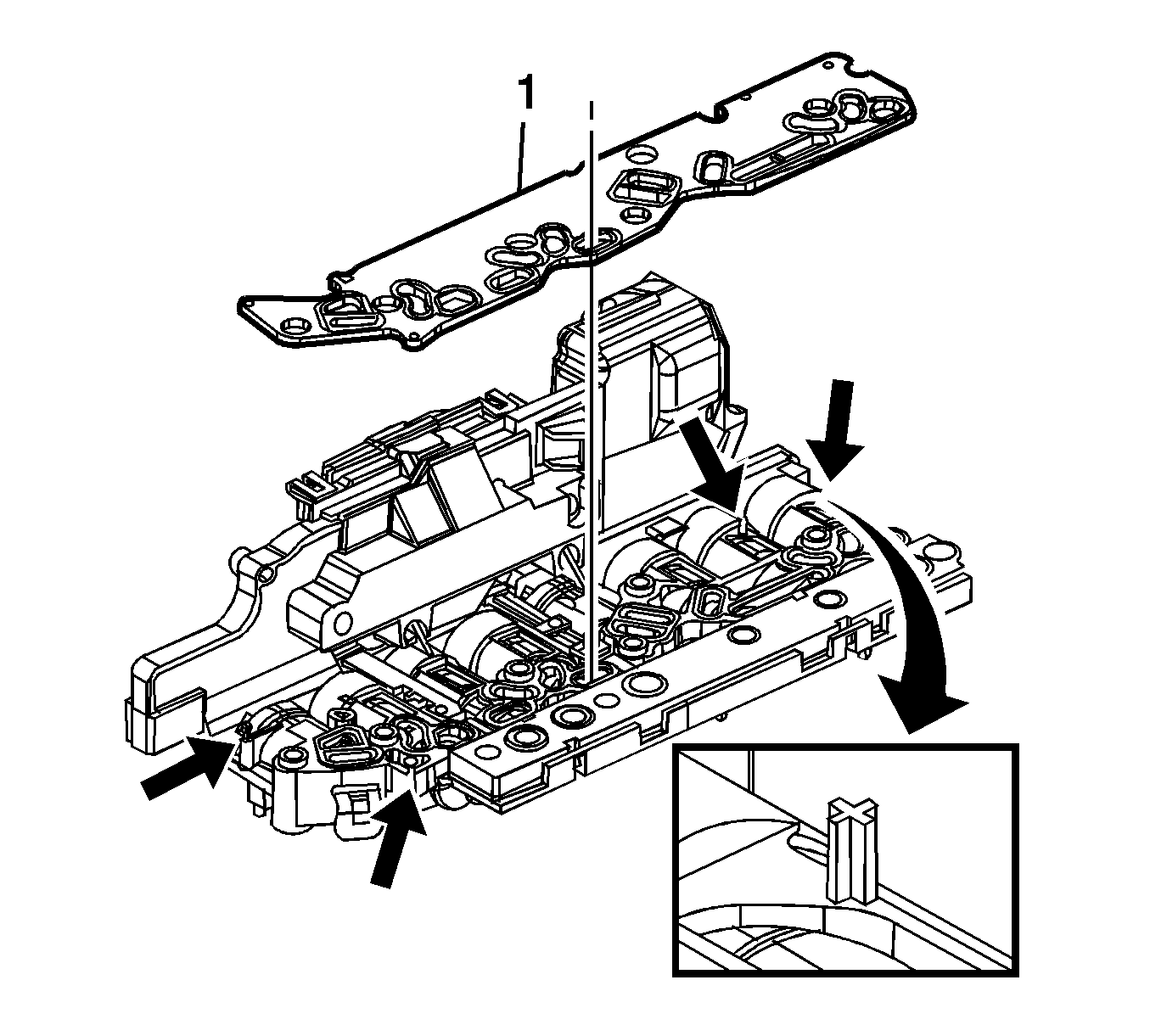
Important: Inspect the 4 filter plate retaining tabs on the control solenoid valve assembly. A broken or missing tab may not adequately secure the filter plate to the control solenoid valve assembly.
Important: Note the locator pin on the control valve lower body assembly.
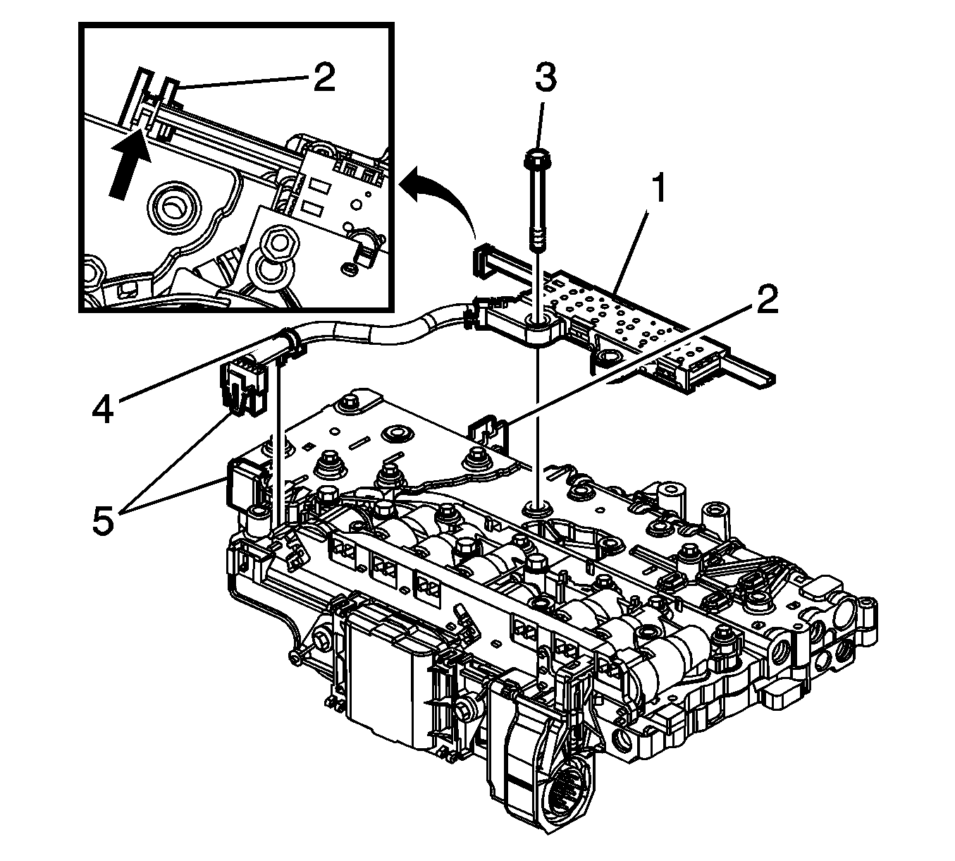
Important: The wiring harness clip (4) on the manual shift shaft position switch does not need to be replaced if damaged or missing. The clip functions only as a manufacturing assembly aid to keep the harness clear during an automated bolt installation process. If the clip is damaged, simply remove and discard.
Notice: Refer to Fastener Notice in the Preface section.
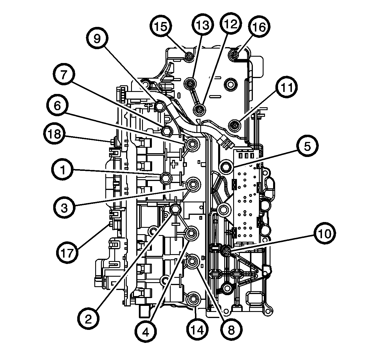
Notice: Bolt torque sequencing is critical to the proper function of the control solenoid valve assembly. Failure to follow the required sequencing may result in transmission malfunction.
Tighten
Tighten bolts to 8 N·m (6 lb ft).
Important: After an internal transmission repair or internal part replacement, the Service Fast Learn Adapt procedure should be performed. Refer to Service Fast Learn Adapts .
