Circuit Description
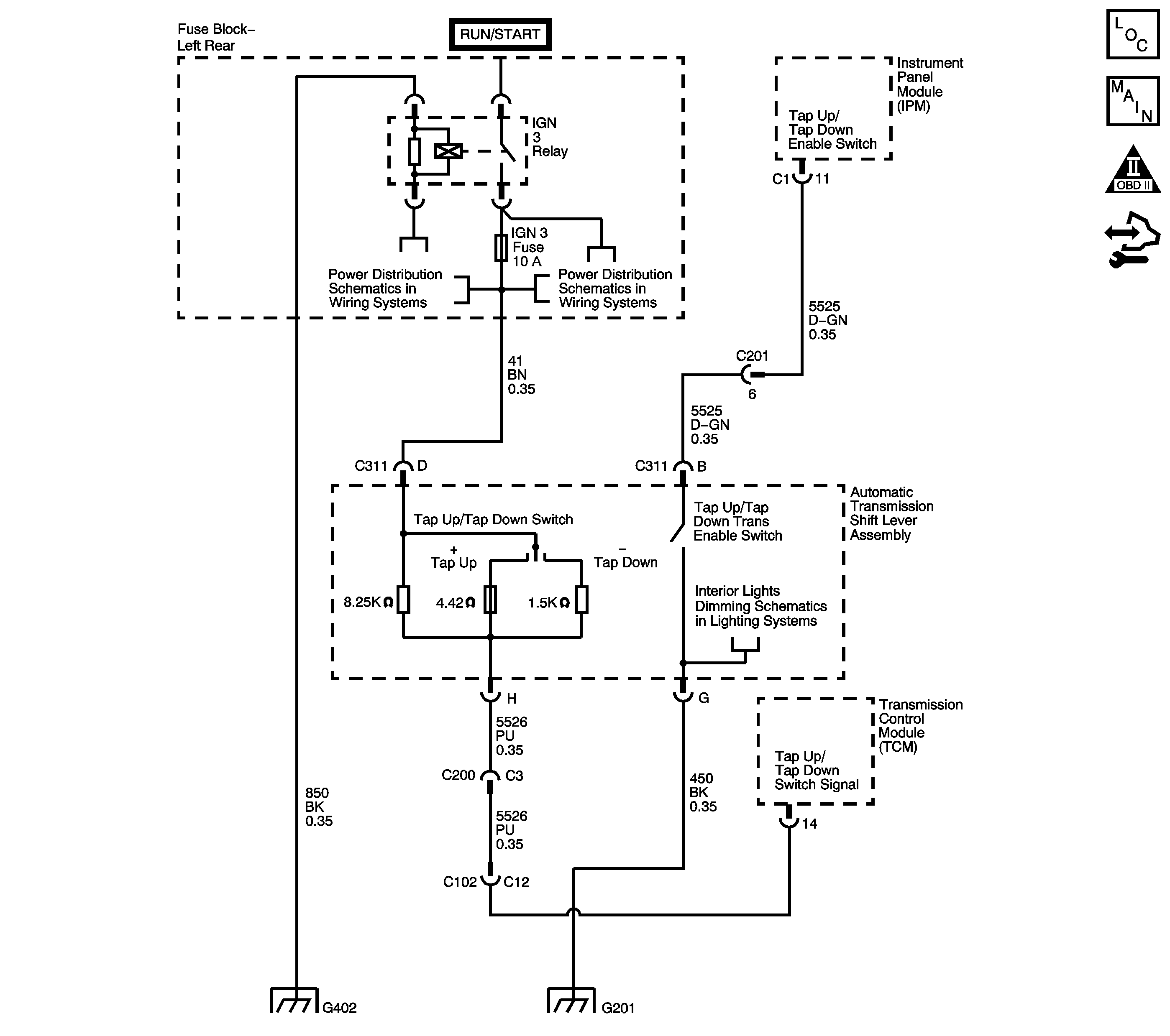
The TAP Shift system allows the driver to manually shift gears by using the Upshift and Downshift positions located on the automatic transmission shift Lever. Pushing the lever to the Upshift position will command an upshift and pushing the lever to the Downshift position will command a downshift. The TAP Shift system is activated when the gear selector is in the manual, M, position and is deactivated in all other positions.
If the transmission control module (TCM) detects TAP enable switch Active and the IMS does not indicate D5, DTC P1876 sets. DTC P1876 is a type C DTC.
DTC Descriptor
This diagnostic procedure supports the following DTC:
DTC P1876 Up and Down Shift Switch Performance - Range Switch Not in D3
Conditions for Running the DTC
| • | No TAP system DTCs P0815, P0816 or P0826. |
| • | No IMS range DTCs P1815, P1820, P1822, P1823, P1825 or P1826. |
| • | The engine run time is greater than 5 seconds. |
| • | No CAN errors present. |
Conditions for Setting the DTC
The TCM detects the TAP enable switch is Active and the IMS range is not D5 for 5 seconds.
Action Taken When the DTC Sets
| • | The TCM does not request the ECM to illuminate the malfunction indicator lamp (MIL). |
| • | The TCM disables TAP Shift operation. |
| • | The TCM records the operating conditions when the Conditions for Setting the DTC are met. The TCM stores this information a Failure Record. |
| • | The TCM stores DTC P1876 in TCM history. |
Conditions for Clearing the DTC
| • | A scan tool can clear the DTC. |
| • | The TCM clears the DTC from TCM history if the vehicle completes 40 warm-up cycles without a non emission related diagnostic fault occurring. |
| • | The TCM cancels the DTC default actions when the ignition is OFF long enough in order to power down the TCM. |
Step | Action | Value(s) | Yes | No |
|---|---|---|---|---|
1 | Did you perform the Diagnostic System Check - Vehicle? | -- | Go to Step 2 | |
2 |
Important: Before clearing the DTC, use the scan tool in order to record the Failure Records. Using the Clear DTC Information function erases the Failure Records from the TCM. Does the scan tool IMS parameter display Drive 5? | -- | Go to Testing for Intermittent Conditions and Poor Connections | Go to Step 3 |
3 |
Does the scan tool IMS A/B/C/P display indicate the specified value for each range? | HI/HI/HI/HI | Go to Step 14 | Go to Step 4 |
4 |
Did the linkage require adjustment? | -- | Go to Step 19 | Go to Step 5 |
5 |
Does the scan tool IMS A/B/C/P display all HI? | -- | Go to Step 6 | Go to Step 10 |
6 |
Did you measure ignition voltage at all four terminals? | -- | Go to Step 7 | Go to Step 11 |
7 | Install a fused jumper wire from the TR signal A circuit of the J 45681 to ground while monitoring the scan tool IMS A/B/C/P display. Refer to Automatic Transmission Inline 20-Way Connector End View . When the TR signal A circuit is grounded, do any other circuits indicate LOW? | -- | Go to Step 12 | Go to Step 8 |
8 | Install a fused jumper wire from the TR signal B circuit of the J 45681 to ground while monitoring the scan tool IMS A/B/C/P display. Refer to Automatic Transmission Inline 20-Way Connector End View . When the TR signal B circuit is grounded, do any other circuits indicate LOW? | -- | Go to Step 12 | Go to Step 9 |
9 | Install a fused jumper wire from the TR signal C circuit of the J 45681 to ground while monitoring the scan tool IMS A/B/C/P display. Refer to Automatic Transmission Inline 20-Way Connector End View . When the TR signal C circuit is grounded, do any other circuits indicate LOW? | -- | Go to Step 12 | Go to Step 13 |
10 | Test the TR signal circuits of the transmission manual shift shaft switch assembly that did not indicate HI for a short to ground between the TCM connector and the AT inline 20-way connector. Refer to Testing for Short to Ground and Wiring Repairs . Did you find and correct the condition? | -- | Go to Step 19 | Go to Step 18 |
11 | Test the TR signal circuits of the transmission manual shift shaft switch assembly that did not indicate ignition voltage for an open between the TCM connector and the AT inline 20-way connector. Refer to Testing for Continuity and Wiring Repairs . Did you find and correct the condition? | -- | Go to Step 19 | Go to Step 18 |
12 | Test the affected signal circuits of the transmission manual shift shaft switch assembly for a shorted together condition between the TCM connector and the AT inline 20-way connector. Refer to Circuit Testing and Wiring Repairs . Did you find and correct the condition? | -- | Go to Step 19 | Go to Step 18 |
13 | Test the TR signal circuits of the transmission manual shift shaft switch assembly for an open or shorted condition between the AT inline 20-way connector and the switch. Refer to Testing for Continuity . Did you find and correct the condition? | -- | Go to Step 16 | Go to Step 17 |
14 | Test the ground circuit of the transmission manual shift shaft switch assembly for an open between the AT inline 20-way connector and the chassis. Refer to Testing for Continuity and Wiring Repairs . Did you find and correct the condition? | -- | Go to Step 19 | Go to Step 15 |
15 | Test the ground circuit of the transmission manual shift shaft switch assembly for an open between the AT inline 20-way connector and the switch. Refer to Testing for Continuity . Did you find and correct the condition? | -- | Go to Step 16 | Go to Step 17 |
16 | Replace the automatic transmission wiring harness assembly. Refer to Transmission Internal Electrical Harness Replacement . Did you complete the replacement? | -- | Go to Step 19 | -- |
17 | Replace the transmission manual shift shaft switch assembly. Refer to Manual Shift Shaft Position Switch Replacement . Is the action complete? | -- | Go to Step 19 | -- |
18 | Replace the TCM. Refer to Control Module References for replacement, setup and programming. Is the action complete? | -- | Go to Step 19 | -- |
19 | Perform the following procedure in order to verify the repair:
Has the test run and passed? | -- | Go to Step 20 | Go to Step 2 |
20 | With the scan tool, observe the stored information, capture info and DTC info. Does the scan tool display any DTCs that you have not diagnosed? | -- | System OK |
