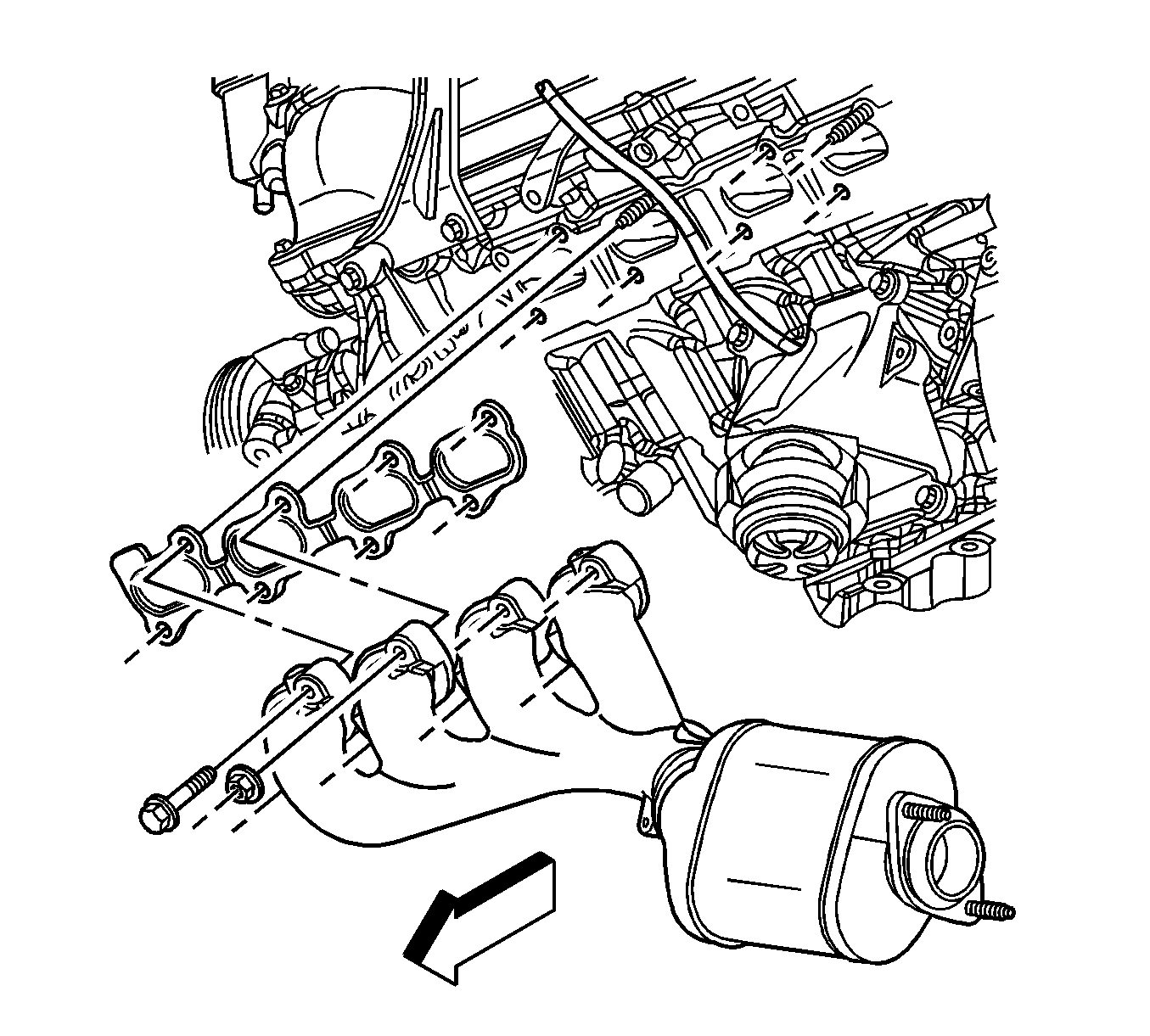
Exhaust Manifold Replacement - Left Side LY7
Removal Procedure
Warning: Refer to Exhaust Service Warning in the Preface section.
Warning: Refer to Protective Goggles and Glove Warning in the Preface section.
- Remove the exhaust manifold heat shield. Refer to Exhaust Manifold Heat Shield Replacement - Left Side.
- Remove the oil level indicator. Refer to Oil Level Indicator and Tube Replacement.
- Remove the catalytic converter nuts.
- Remove the exhaust manifold bolts.
- Remove the exhaust manifold and discard the exhaust manifold gasket.
- Clean and inspect the exhaust manifold. Refer to Exhaust Manifold Cleaning and Inspection - Left Side.
Note: Do not reuse the gasket.
Installation Procedure
- Install the catalytic converter seal/heat shield to the catalytic converter.
- Install a NEW exhaust manifold gasket to the exhaust manifold.
- Install the exhaust manifold with the gasket to the catalytic converter and the cylinder head.
- Install the exhaust manifold bolts and tighten to 20 N·m (15 lb ft).
- Install the catalytic converter nuts and tighten to 50 N·m (37 lb ft).
- Install the oil level indicator. Refer to Oil Level Indicator and Tube Replacement.
- Install the exhaust manifold heat shield. Refer to Exhaust Manifold Heat Shield Replacement - Left Side.
Note: Inspect the catalytic converter seal/heat shield sealing surface. Replace the seal/heat shield if the sealing surface is worn or damaged.
Caution: Refer to Fastener Caution in the Preface section.
Exhaust Manifold Replacement - Left Side V8 and LHD
Removal Procedure
Warning: Refer to Exhaust Service Warning in the Preface section.
Warning: Refer to Protective Goggles and Glove Warning in the Preface section.
- Remove the air cleaner housing assembly. Refer to Air Cleaner Assembly Replacement.
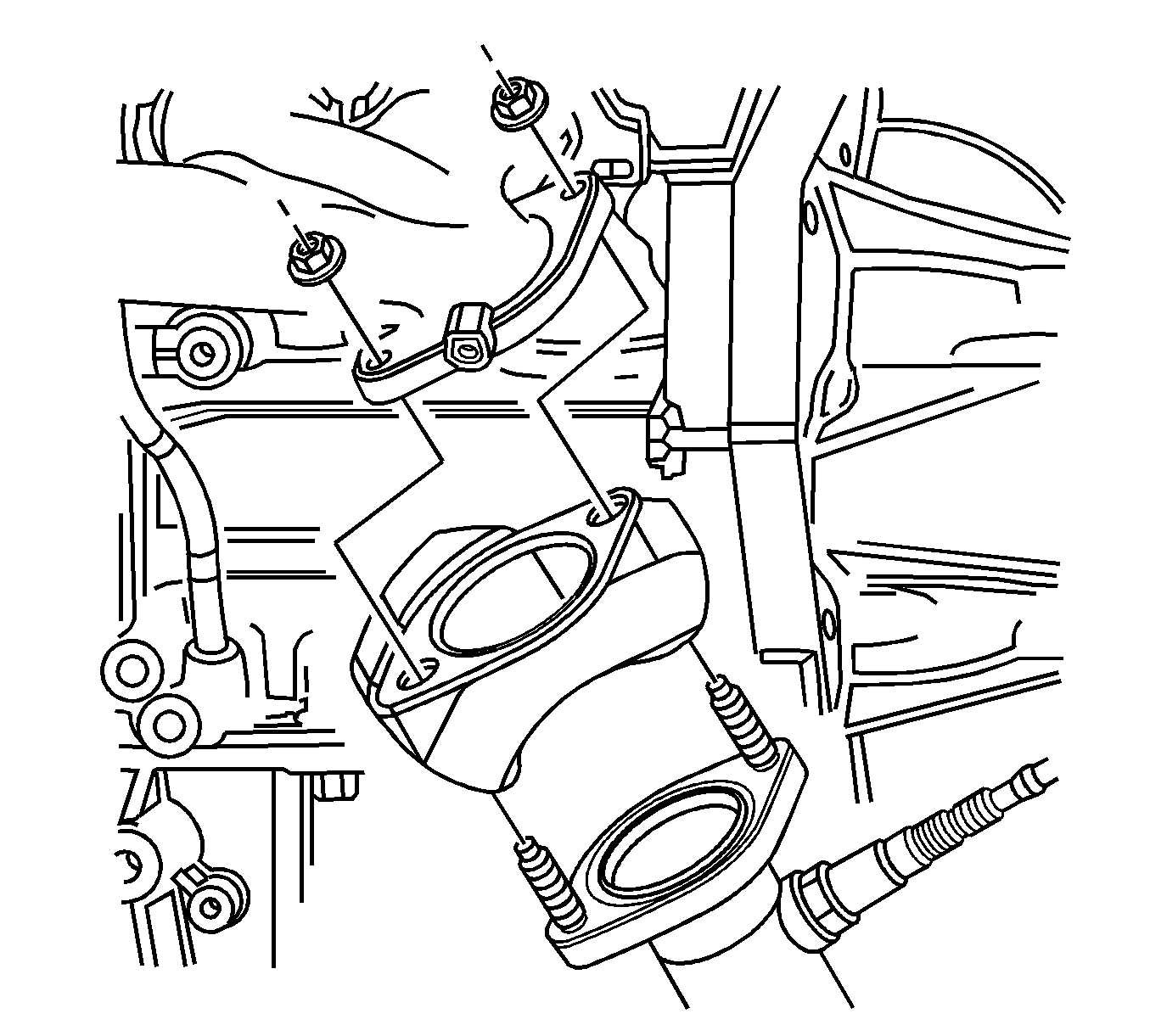
- Remove the nut securing the air conditioning (A/C) lines to the left hand shock tower.
- Remove the front upper heat shield bolt.
- Disconnect the master cylinder electrical connector.
- Remove the master cylinder mounting nuts.
- Remove the rear upper heat shield bolt.
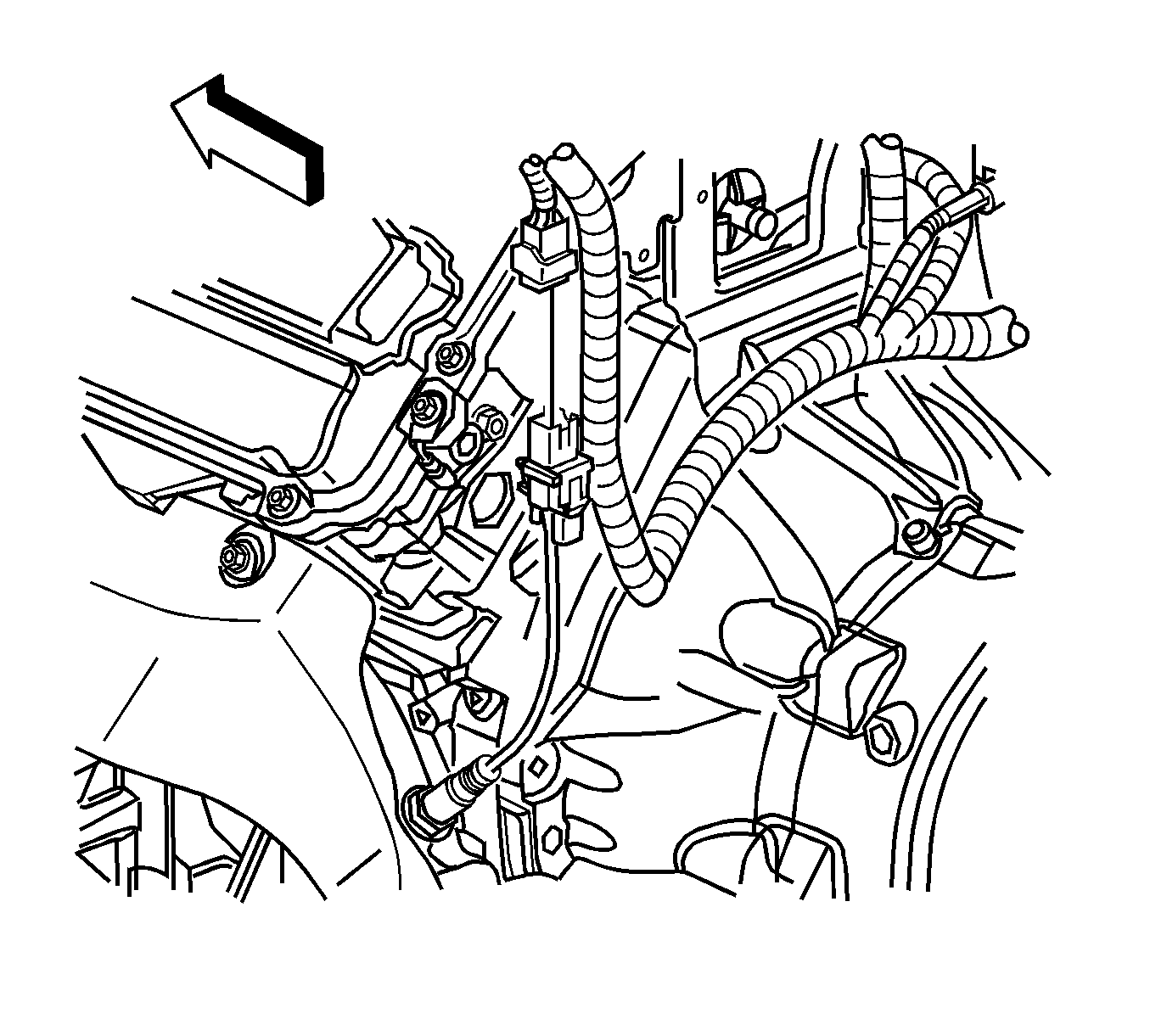
- Disconnect both Bank 2 heated oxygen sensor pigtail connectors from the wiring harness connector.
- Remove the power steering gear. Refer to Steering Gear Replacement.
- Remove the lower intermediate steering shaft. Refer to Lower Intermediate Steering Shaft Replacement.
- Remove the exhaust system. Refer to Exhaust System Replacement.
- Remove the Bank 2, Sensor 1 heated oxygen sensor. Refer to Heated Oxygen Sensor Replacement - Bank 2 Sensor 1.
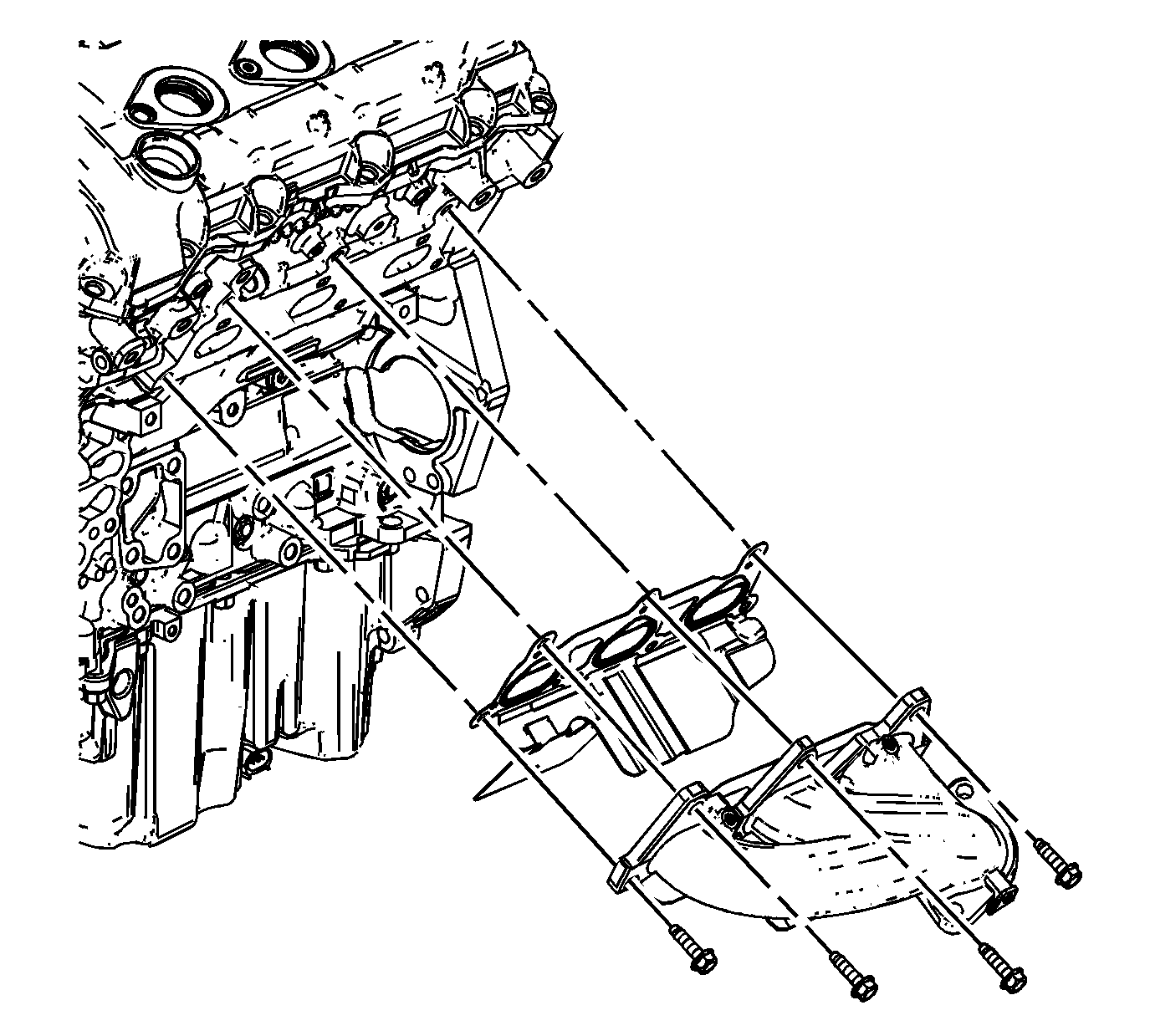
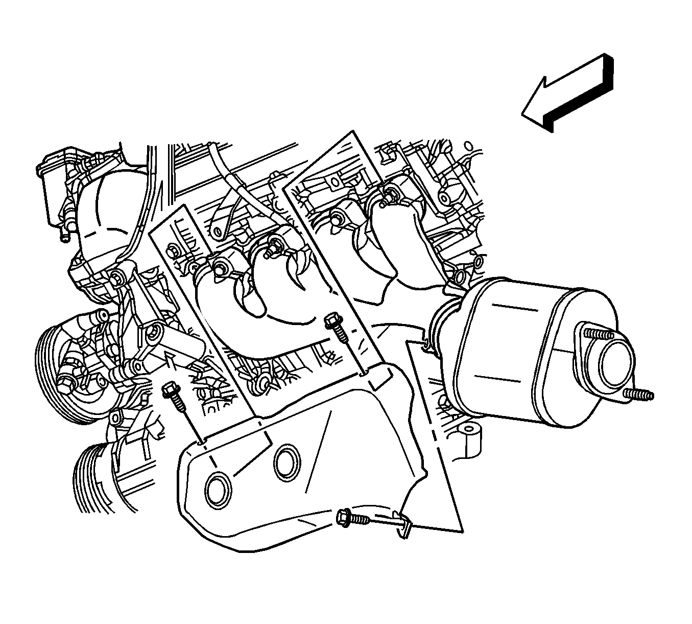
- Remove the remaining exhaust manifold heat shield bolt and remove the shield.
- Remove the left exhaust manifold bolts and nuts. Discard the exhaust manifold bolts.
- Remove the exhaust manifold studs, if necessary.
- Remove the left exhaust manifold and gasket from the engine. Do not reuse the gasket.
- Clean and inspect the left exhaust manifold. Refer to Exhaust Manifold Cleaning and Inspection - Left Side.
Position the lines aside to provide tool access to the exhaust manifold shield front bolt.
Position the master cylinder towards the engine to gain tool access to the exhaust manifold shield rear bolt.
Installation Procedure
- Use a NEW exhaust manifold gasket.
- Position the left exhaust manifold and gasket to the left cylinder head.
- Install the left exhaust manifold studs, nuts and NEW bolts.
- Install the exhaust manifold heat shield to the manifold with the lower bolt and tighten to 10 N·m (89 lb in).
- Install the Bank 2, Sensor 1 heated oxygen sensor. Refer to Heated Oxygen Sensor Replacement - Bank 2 Sensor 1.
- Install the exhaust system. Refer to Exhaust System Replacement.
- Install the lower intermediate steering shaft. Refer to Lower Intermediate Steering Shaft Replacement.
- Install the power steering gear. Refer to Steering Gear Replacement.
- Lower the vehicle.
- Connect the heated oxygen sensor pigtail connectors to the wiring harness connector.
- Install the rear upper heat shield bolt and tighten to 10 N·m (89 lb in).
- Install the master cylinder and connect the master cylinder electrical connector. Refer to Master Cylinder Replacement.
- Install the front upper heat shield bolt and tighten to 10 N·m (89 lb in).
- Install the nut securing the A/C lines to the left hand shock tower and tighten to 10 N·m (89 lb in).
- Install the air cleaner housing assembly. Refer to Air Cleaner Assembly Replacement.
Caution: Refer to Fastener Caution in the Preface section.
| • | Tighten the exhaust manifold studs to 6 N·m (53 lb in). |
| • | Tighten the exhaust manifold nuts to 25 N·m (18 lb ft). |
| • | Tighten the exhaust manifold bolts to 25 N·m (18 lb ft). |
