Exhaust Manifold Replacement - Right Side LP1, LY7, LLT
Removal Procedure
Caution: Refer to Exhaust Service Caution in the Preface section.
Caution: Refer to Protective Goggles and Glove Caution in the Preface section.
- Remove the exhaust manifold heat shield. Refer to Exhaust Manifold Heat Shield Replacement - Right Side .
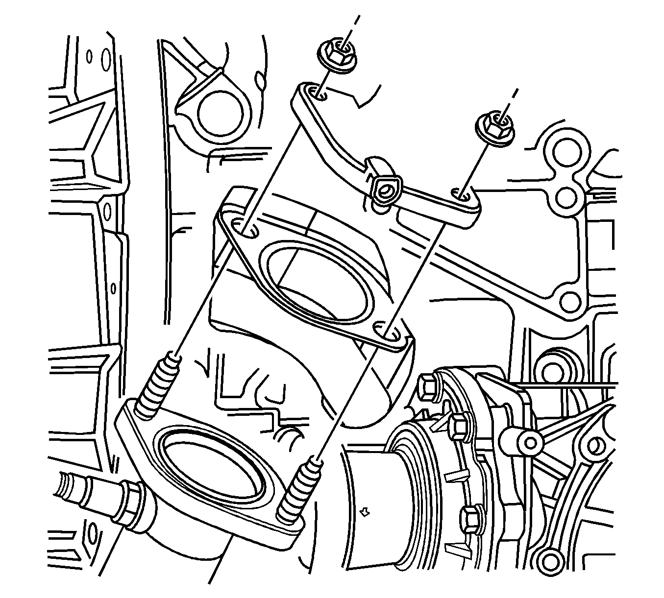
- Remove the catalytic converter nuts.
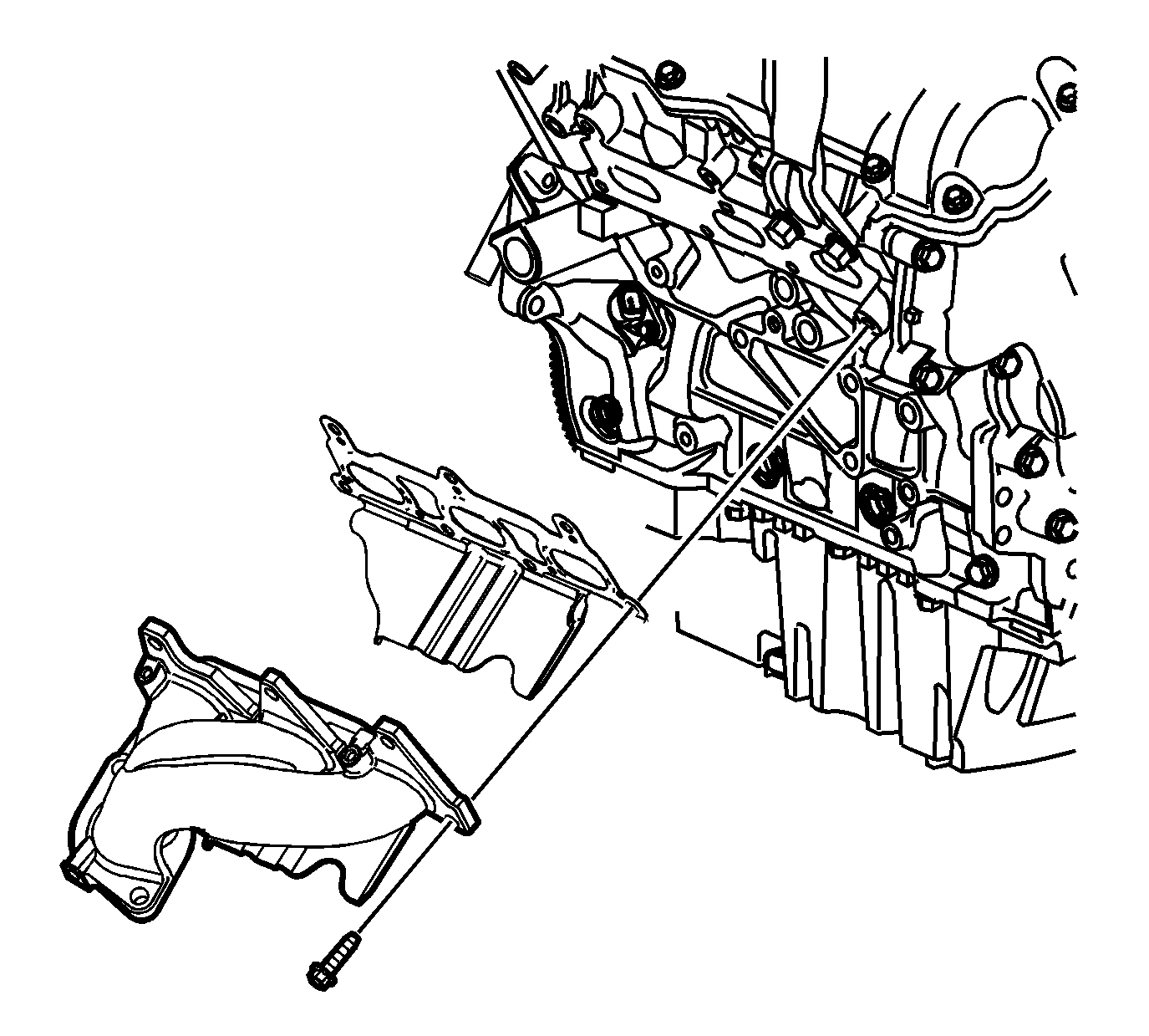
- Remove the exhaust manifold bolts.
- Remove the exhaust manifold and discard the exhaust manifold gasket.
- Clean and inspect the exhaust manifold. Refer to Exhaust Manifold Cleaning and Inspection - Left Side .
Important: Do not reuse the gasket.
Installation Procedure
- Install the catalytic converter seal/heat shield to the catalytic converter.
- Install a NEW exhaust manifold gasket to the exhaust manifold.
- Install the exhaust manifold with the gasket to the catalytic converter and the cylinder head.
- Install the exhaust manifold bolts.
- Install the catalytic converter nuts.
- Install the exhaust manifold heat shield. Refer to Exhaust Manifold Heat Shield Replacement - Right Side .
Important: Inspect the catalytic converter seal/heat shield sealing surface. Replace the seal/heat shield if the sealing surface is worn or damaged.

Notice: Refer to Fastener Notice in the Preface section.
Tighten
Tighten the exhaust manifold bolts to 20 N·m (15 lb ft).

Tighten
Tighten the catalytic converter nuts to 50 N·m (37 lb ft).
Exhaust Manifold Replacement - Right Side V8 and LHD
Removal Procedure
Caution: Refer to Exhaust Service Caution in the Preface section.
Caution: Refer to Protective Goggles and Glove Caution in the Preface section.
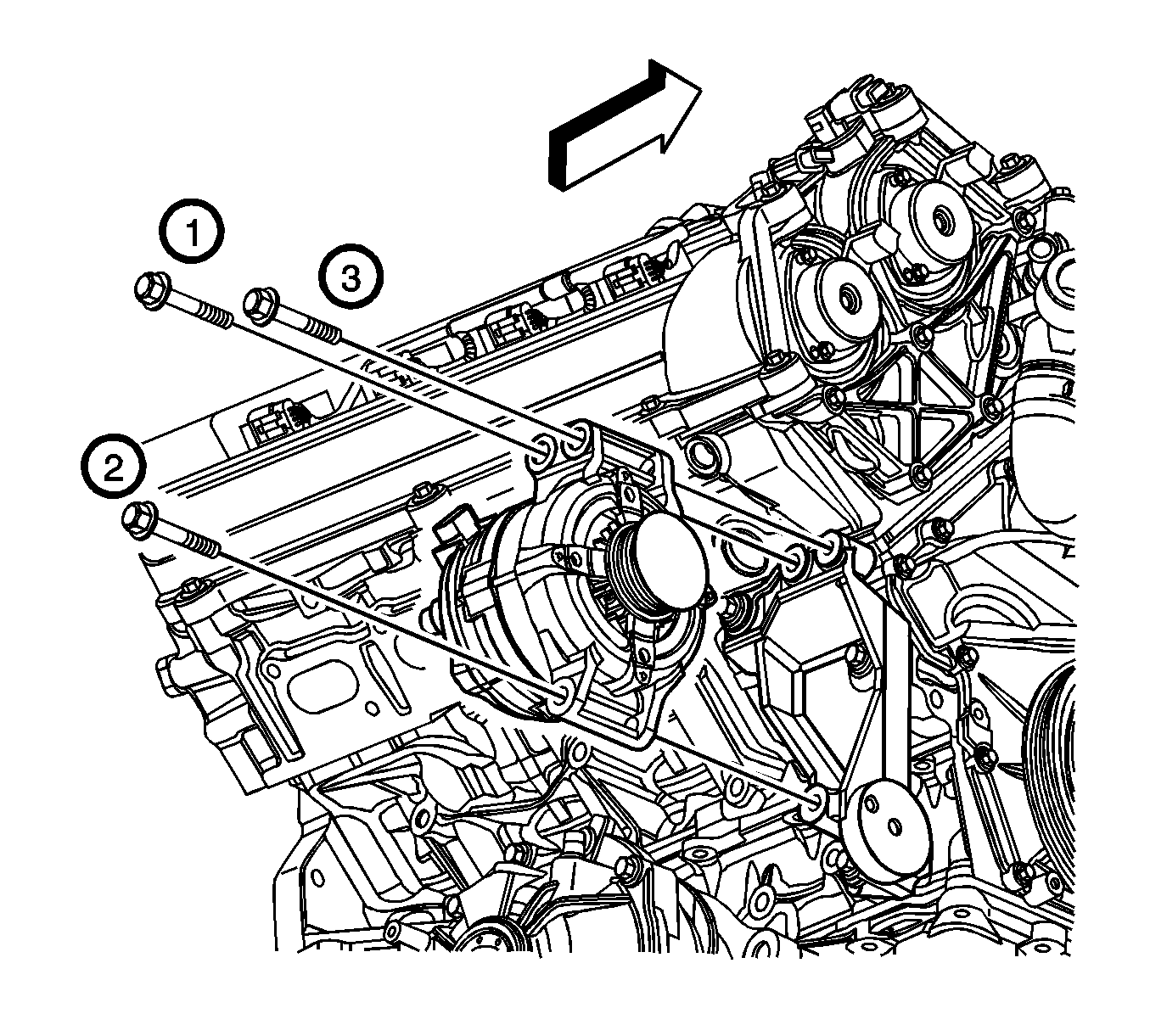
- Remove the generator bolts (1--3) and remove the generator assembly. Refer to Generator Replacement .
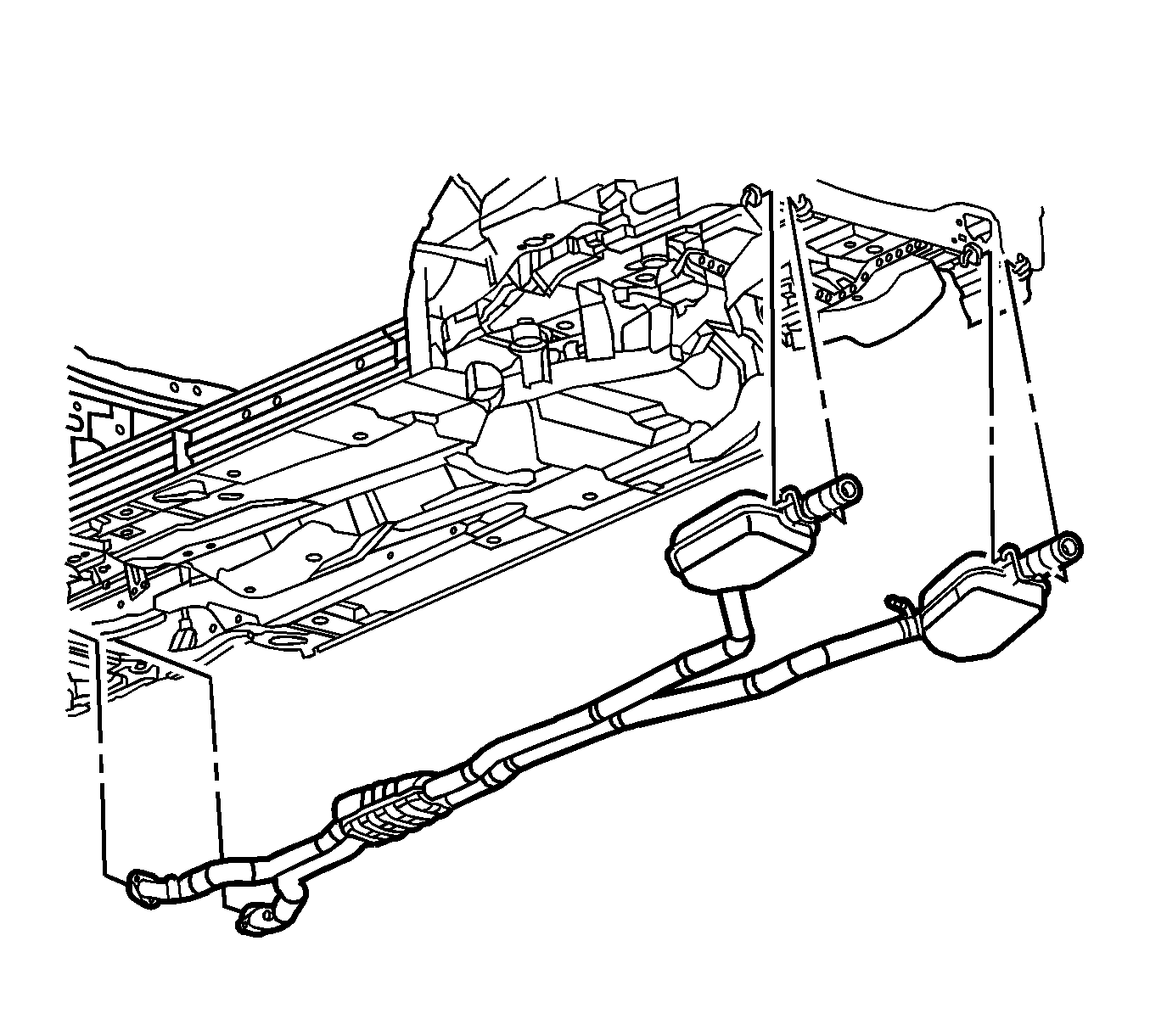
- With the aid of an assistant, remove the exhaust system. Refer to Exhaust System Replacement .
- Disconnect the Bank 1, Sensor 1 heated oxygen sensor pigtail from the wiring harness connector (1).
- If the vehicle is equipped with all wheel drive (AWD), remove the right outer tie rod end from the steering knuckle to gain access to the upper rear exhaust manifold shield bolt. Refer to Rack and Pinion Outer Tie Rod End Replacement .
- Remove the bolts securing the engine wiring harness bracket to the right cylinder head.
- Remove the right exhaust manifold heat shield bolts.
- Reposition the shield forward in vehicle in the area where the generator mounts, to gain access to the exhaust manifold bolts.
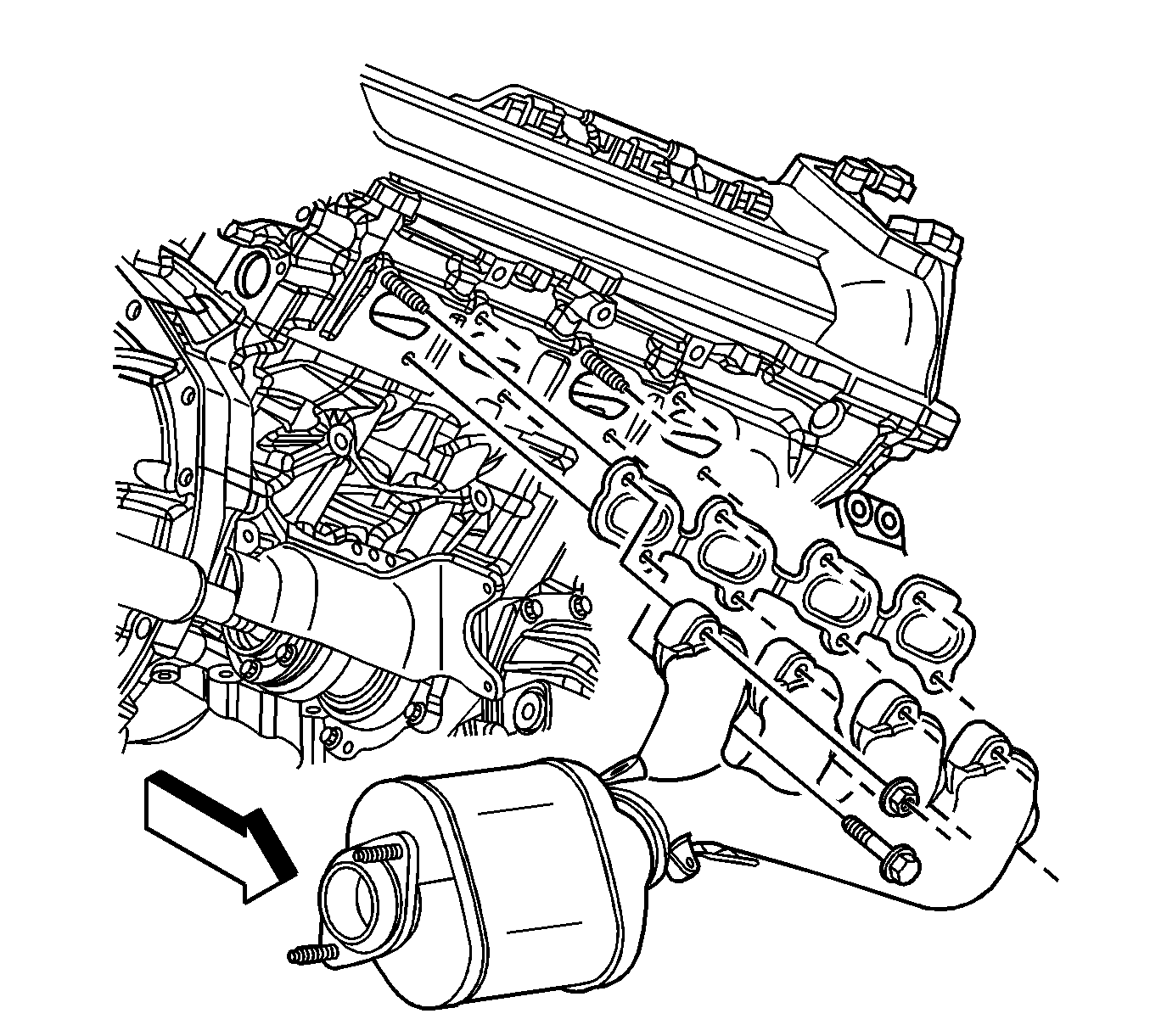
- Remove the right exhaust manifold bolts and nuts. Discard the exhaust manifold bolts.
- Remove the exhaust manifold studs, if necessary.
- Remove the right exhaust manifold and the gasket from the engine. Do not reuse the gasket.
- If necessary, remove the exhaust manifold heat shield from the vehicle.
- Remove the heated oxygen sensor, if necessary, from the exhaust manifold. Refer to Heated Oxygen Sensor Replacement - Bank 1 Sensor 1 for the 4.6L engine.
- Clean and inspect the right exhaust manifold. Refer to Exhaust Manifold Cleaning and Inspection - Right Side for the 4.6L engine.
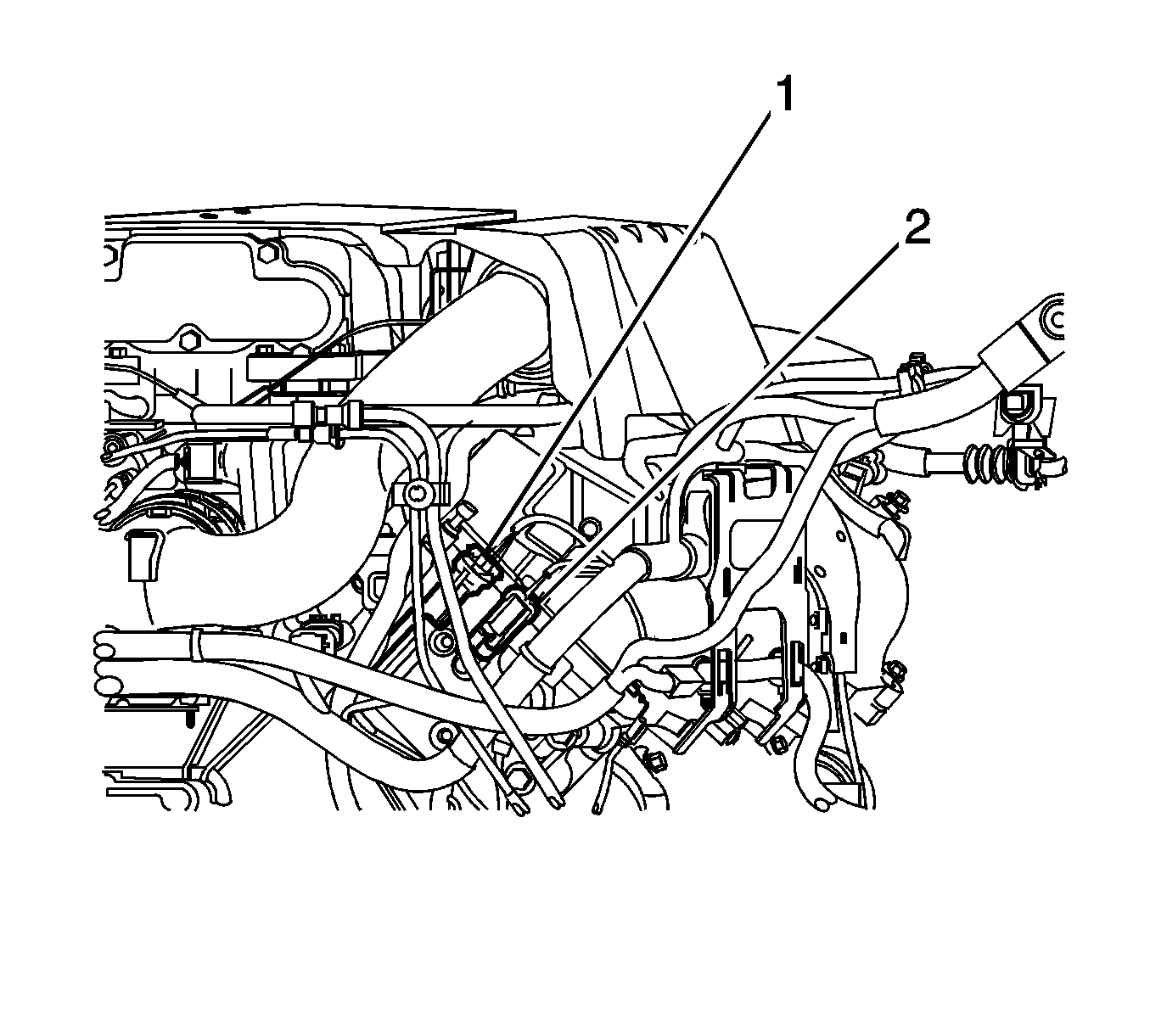
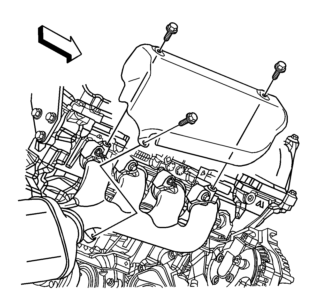
Position the wire harness bracket aside.
Installation Procedure
- Install the heated oxygen sensor to the exhaust manifold, if previously removed. Refer to Heated Oxygen Sensor Replacement - Bank 1 Sensor 1 for the 4.6L engine.
- If previously removed, install the exhaust manifold heat shield to the vehicle.
- Install a NEW exhaust manifold gasket over the cylinder head studs.
- Position the right exhaust manifold and gasket to the right cylinder head.
- Install the right exhaust manifold studs, nuts and NEW bolts.
- Connect the Bank 1, Sensor 1 heated oxygen sensor electrical connector.
- Install the exhaust manifold heat shield to the exhaust manifold. Install the exhaust manifold heat shield bolts.
- Install the bolts securing the engine wiring harness bracket to the right cylinder head.
- If previously removed, install the right outer tie rod end to the steering knuckle. Refer to Rack and Pinion Outer Tie Rod End Replacement .
- With the aid of an assistant, install the exhaust system. Refer to Exhaust System Replacement .
- Install the generator and generator bolts (1--3). Refer to Generator Replacement .

Place the shield forward in vehicle where the generator mounts to allow installation of the exhaust manifold.
Notice: Refer to Fastener Notice in the Preface section.
Tighten
| • | Tighten the exhaust manifold studs to 6 N·m (53 lb in). |
| • | Tighten the exhaust manifold nuts to 25 N·m (18 lb ft). |
| • | Tighten the exhaust manifold bolts to 25 N·m (18 lb ft). |

Tighten
Tighten the exhaust manifold heat shield bolts to 10 N·m (89 lb in).
Tighten
Tighten the engine wiring harness bracket bolts to 45 N·m (33 lb ft).


