Removal Procedure
Notice:
• Turn the ignition OFF when installing or removing the control module connectors and disconnecting or reconnecting the power to the control module (battery cable, powertrain control module (PCM)/engine control module (ECM)/transaxle control module
(TCM) pigtail, control module fuse, jumper cables, etc.) in order to prevent internal control module damage. • Control module damage may result when the metal case contacts battery voltage. DO NOT contact the control module metal case with battery voltage when servicing a control module, using battery booster cables, or when charging the vehicle battery. • In order to prevent any possible electrostatic discharge damage to the control module, do no touch the connector pins or the soldered components on the circuit board. • Remove any debris from around the control module connector surfaces before servicing the control module. Inspect the control module connector gaskets when diagnosing or replacing the control module. Ensure that the gaskets are installed correctly.
The gaskets prevent contaminant intrusion into the control module. • The replacement control module must be programmed.
Important: It is necessary to record the remaining engine oil life. If the replacement module is not programed with the remaining engine oil life, the engine oil life will default to 100 percent. If the replacement module is not programmed with the remaining engine oil life, the engine oil will need to be changed at 5000 km (3,000 mi) from the last engine oil change.
Important: It is necessary to record the remaining automatic transmission fluid life. If the replacement module is not programed with the remaining automatic transmission fluid life, the automatic transmission fluid life will default to 100 percent. If the replacement module is not programmed with the remaining automatic transmission fluid life, the automatic transmission fluid will need to be changed at 83000 km (50,000 mi) from the last automatic transmission fluid change.
- Using a scan tool, retrieve the percentage of remaining engine oil and the remaining automatic transmission fluid life. Record the remaining engine oil and the remaining automatic transmission fluid life.
- Turn the ignition OFF.
- Use a DVOM in order to measure the main relay circuit voltage at the ECM fuse in the underhood fuse block. Refer to Electrical Center Identification Views .
- Disconnect the battery negative cable. Refer to Battery Negative Cable Disconnection and Connection .
- Remove the ECM fuse in the underhood fuse block. Refer to Electrical Center Identification Views .
- Remove the TCM/IPC fuse in the underhood fuse block. Refer to Electrical Center Identification Views in Wiring Systems.
- Remove the ECM/TCM fuse in the underhood fuse block. Refer to Electrical Center Identification Views in Wiring Systems.
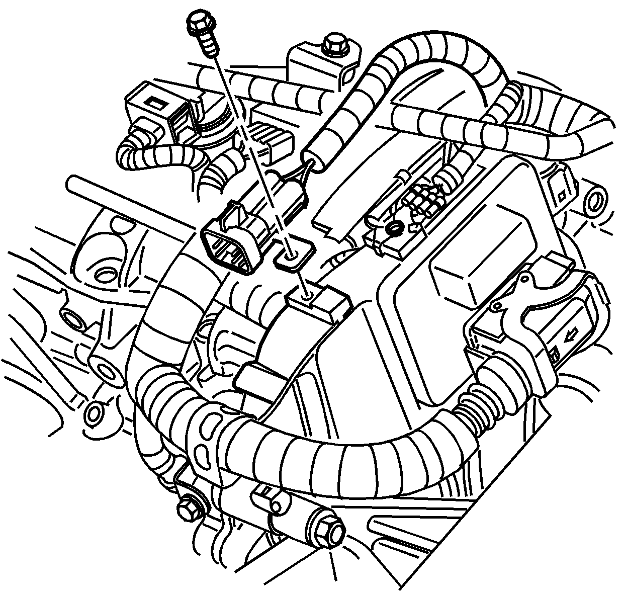
- Unlock the chassis side (upper) ECM electrical connector.
- Remove the body side (upper) ECM connector.
- Unlock and remove the engine side (lower) ECM connector.
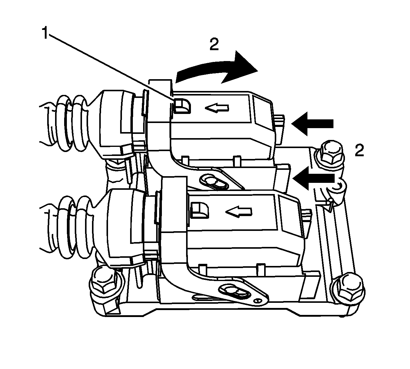
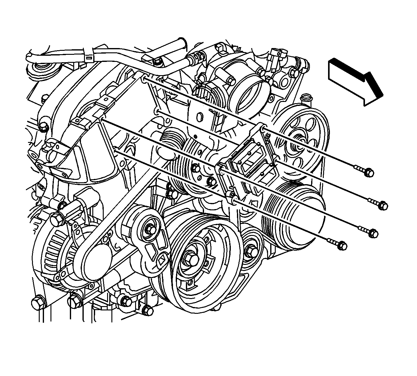
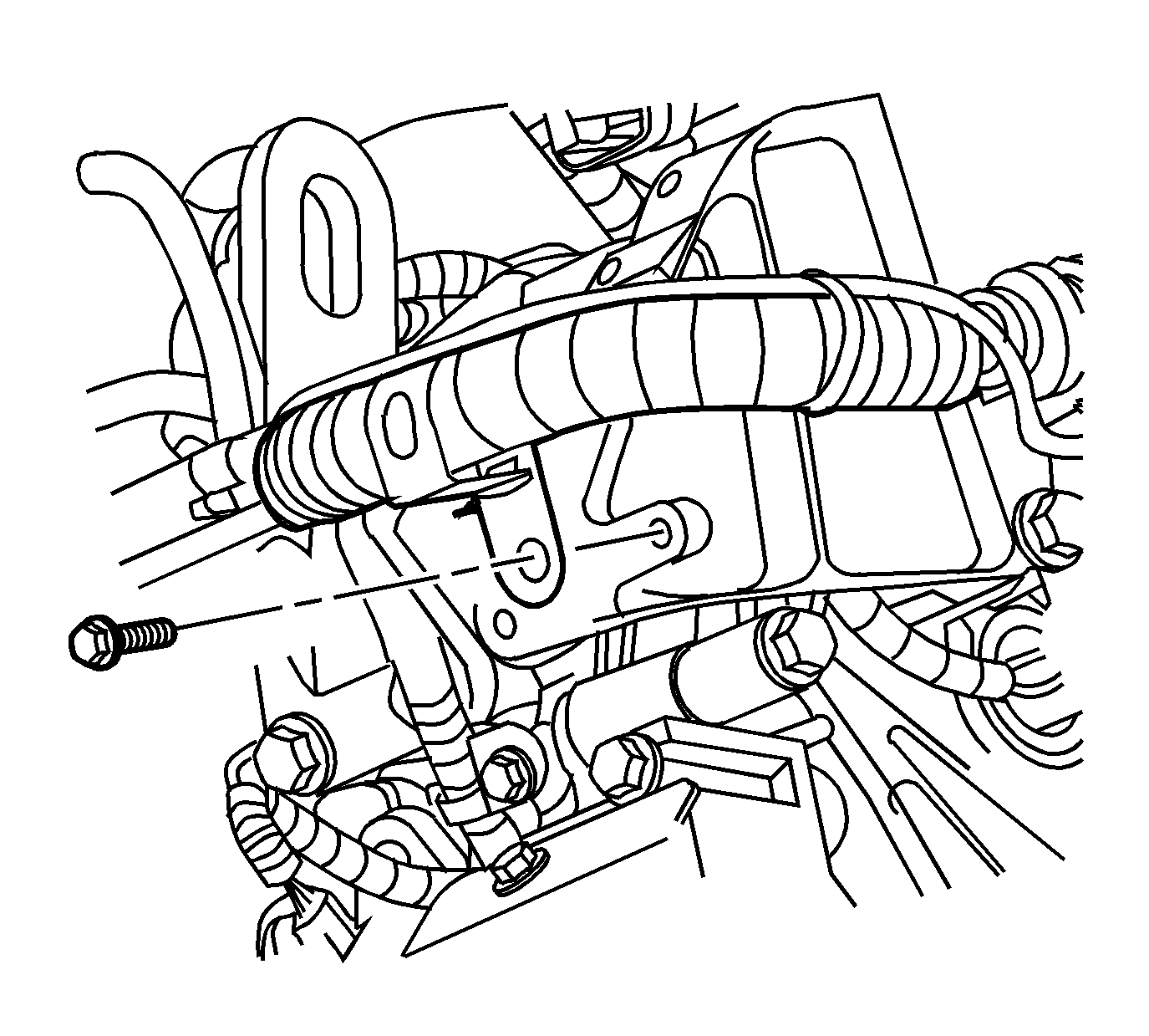
- Remove the ECM redundant ground wire and bolt (2) from the ECM.
- Remove the ECM bolts.
- Remove the ECM.
- If you are replacing the ECM bracket, perform the following steps:
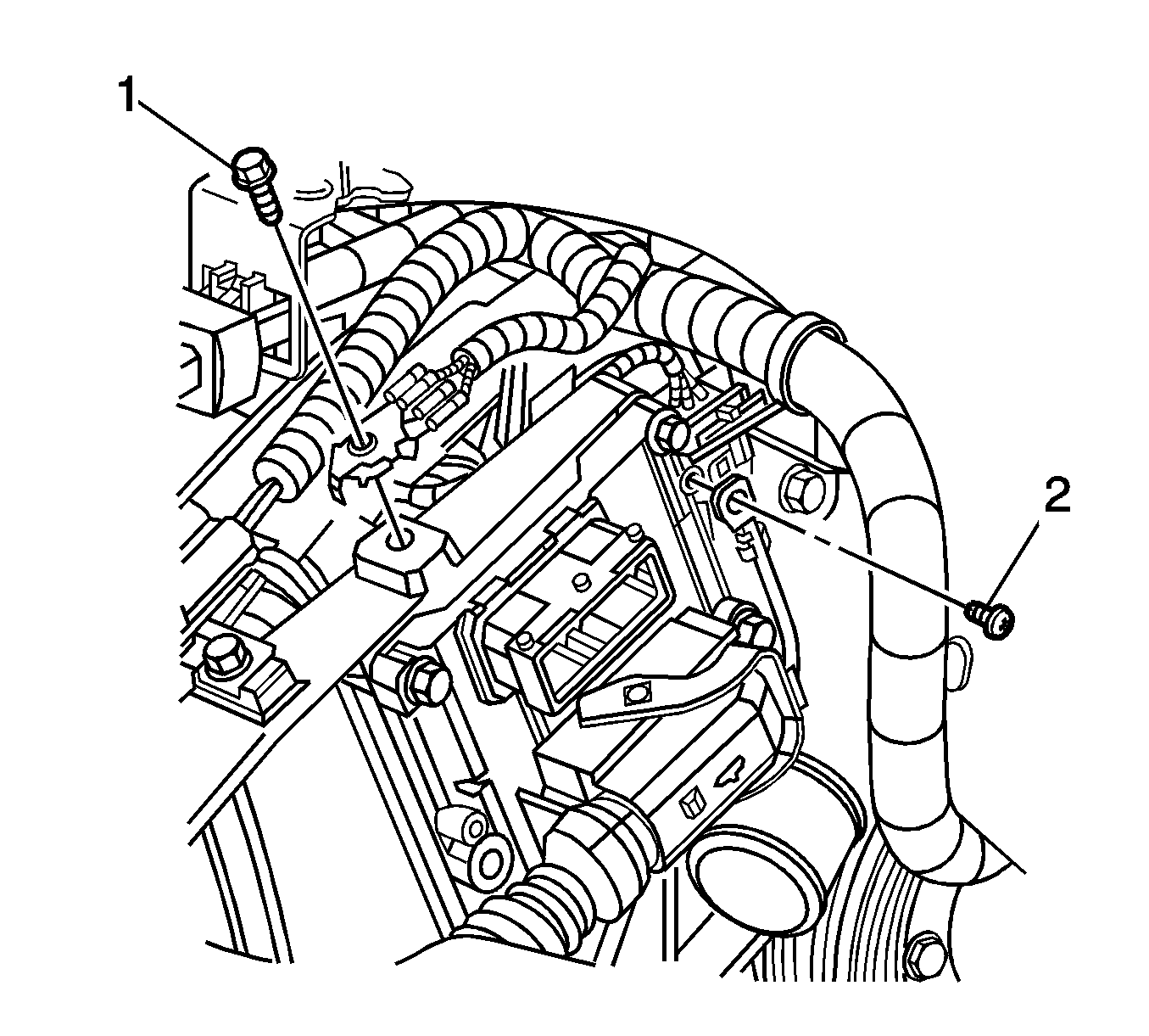
- Remove the electrical connector bracket and bolt from the ECM bracket.
- Remove the ground wire and bolt from the ECM bracket.
- Remove the wire harness retainer and bolt from the side of the ECM bracket.
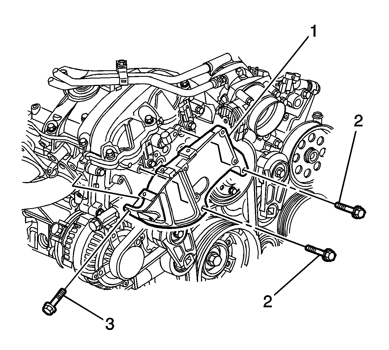
- Remove the ECM bracket bolts (2 and 3).
- Remove the ECM bracket (1).
Important: Ensure that there is no main relay circuit voltage (ECM Fuse).
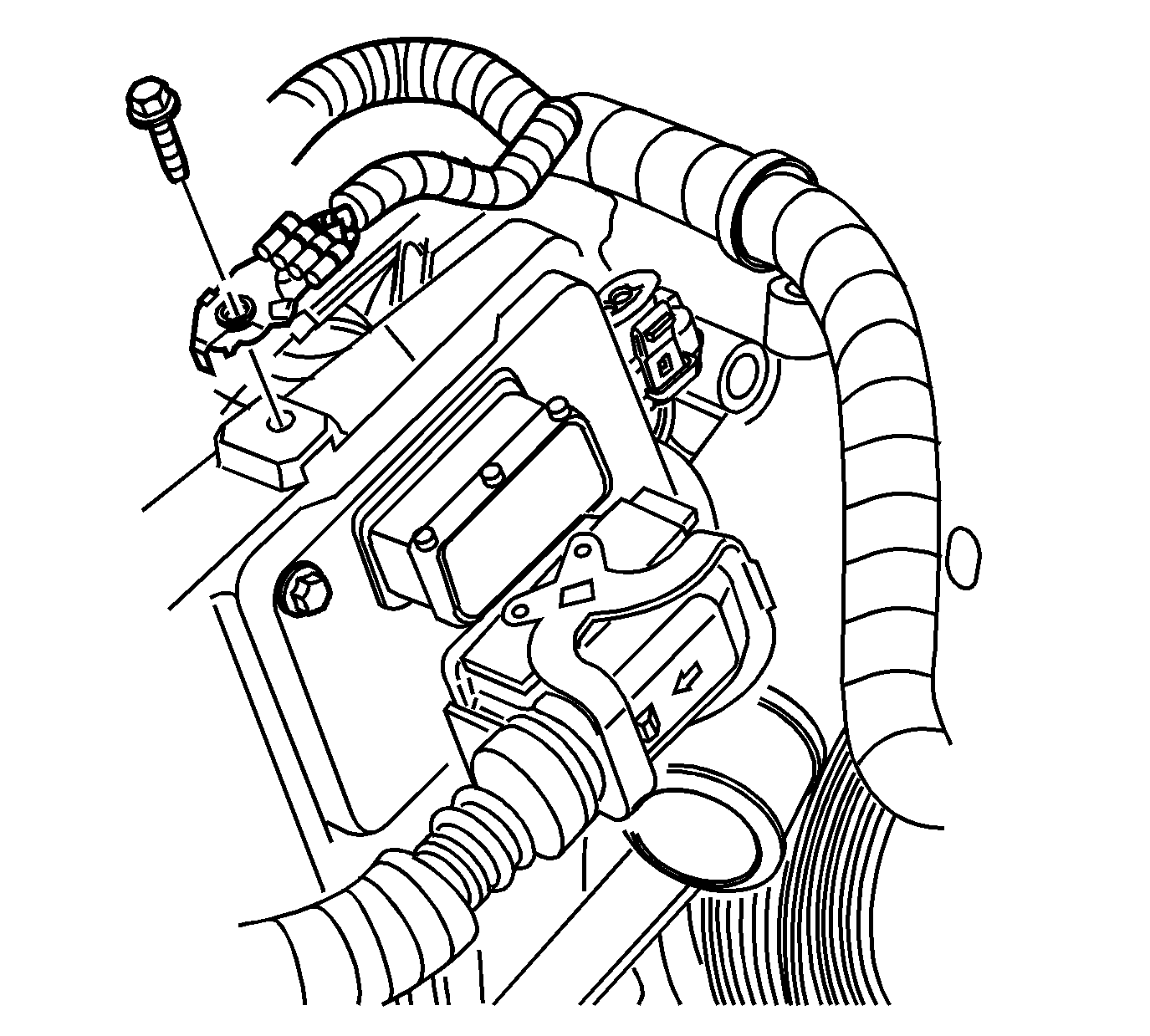
| 8.1. | Depress the ECM electrical connector lever lock (1). |
| 8.2. | Simultaneously rotate the ECM connector clamp lever and depress the lock slide (2). |
Notice: In order to prevent any possible electrostatic discharge damage to the ECM, do not touch the connector pins.
Installation Procedure
- Install the ECM bracket (1).
- Install the ECM bracket bolts (2 and 3).
- Tighten the ECM bracket bolt (2) to 10 N·m (89 lb in).
- Tighten the ECM bracket bolts (3) to 23 N·m (17 lb ft).
- Install the wire harness retainer and bolt (2) to the side of the ECM bracket.
- Install the electrical connector bracket and bolt to the ECM bracket.
- Install the wiring harness ground wire and bolt to the ECM bracket.
- Install the ECM.
- Install the ECM bolts.
- Install the ECM redundant ground and bolt (2) to the ECM.
- Install the engine side (lower) ECM connector.
- Install the body side (upper) ECM connector.
- Install the ECM/TCM fuse in the underhood fuse block. Refer to Electrical Center Identification Views .
- Install the TCM/IPC fuse in the underhood fuse block. Refer to Electrical Center Identification Views .
- Install the ECM fuse in the underhood fuse block. Refer to Electrical Center Identification Views .
- Connect the battery negative cable to the battery. Refer to Battery Negative Cable Disconnection and Connection .
- Program the ECM. Refer to Service Programming System (SPS) .
- If you encounter an ECM programming error, with a display message of "Starting Disabled, Remove Key" on the driver information center, with a diagnostic test code (DTC) of P1631, perform the "10-Minute Relearn Procedure" found in Programming Theft Deterrent System Components. Refer to Programming Theft Deterrent System Components . Additional information can be found in service bulletin number 05524 A.
- Turn OFF the ignition for at least 5 seconds after the programming event is complete.
- Perform the idle learn procedure. Refer to Idle Learn .
- Use the scan tool to clear all DTCs.
- Refer to Control Module References for programming and setup information.
Notice: Refer to Fastener Notice in the Preface section.
Tighten
Tighten
Tighten the wire harness retainer bolt to 23 N·m (17 lb ft).
Tighten
Tighten the electrical connector bracket bolt to 10 N·m (89 lb in).
Tighten
Tighten the wiring harness ground wire bolt 10 N·m (89 lb in).
Notice: In order to prevent any possible electrostatic discharge damage to the ECM, do not touch the connector pins.
Tighten
Tighten the ECM bolts to 10 N·m (89 lb in).
Tighten
Tighten the ECM redundant ground wire bolt to 5 N·m (44 lb in).
