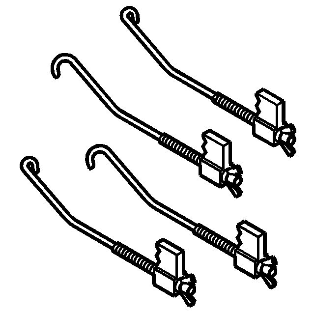
Special Tools
| • | EN 46108 Timing Chain Retention Tool |
| • | EN 46111 Crankshaft Rotation Socket |
Removal Procedure
- Remove the upper intake manifold with the lower intake manifold. Refer to Lower Intake Manifold Replacement.
- Remove the left bank camshaft cover. Refer to Camshaft Cover Replacement - Left Side.
- Remove the camshaft sensors. Refer to Camshaft Position Sensor Replacement - Bank 2 (Left Side) Exhaust and Camshaft Position Sensor Replacement - Bank 2 (Left Side) Intake.
- Remove the camshaft position actuator solenoid. Refer to Camshaft Position Actuator Solenoid Valve Solenoid Replacement - Bank 2 (Left Side) Intake.
- Remove the crankshaft balancer. Refer to Crankshaft Balancer Removal.
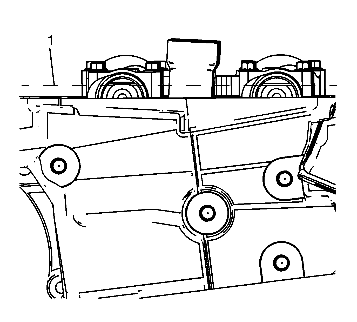
- Rotate the crankshaft using the crankshaft balancer bolt until the camshafts are in a neutral (low tension) position. The camshaft flats will be parallel with the camshaft cover rail (1).
- Loosen the camshaft position actuator bolt.
- Install the EN 46108 (1 and 2) in order to retain the timing chain.
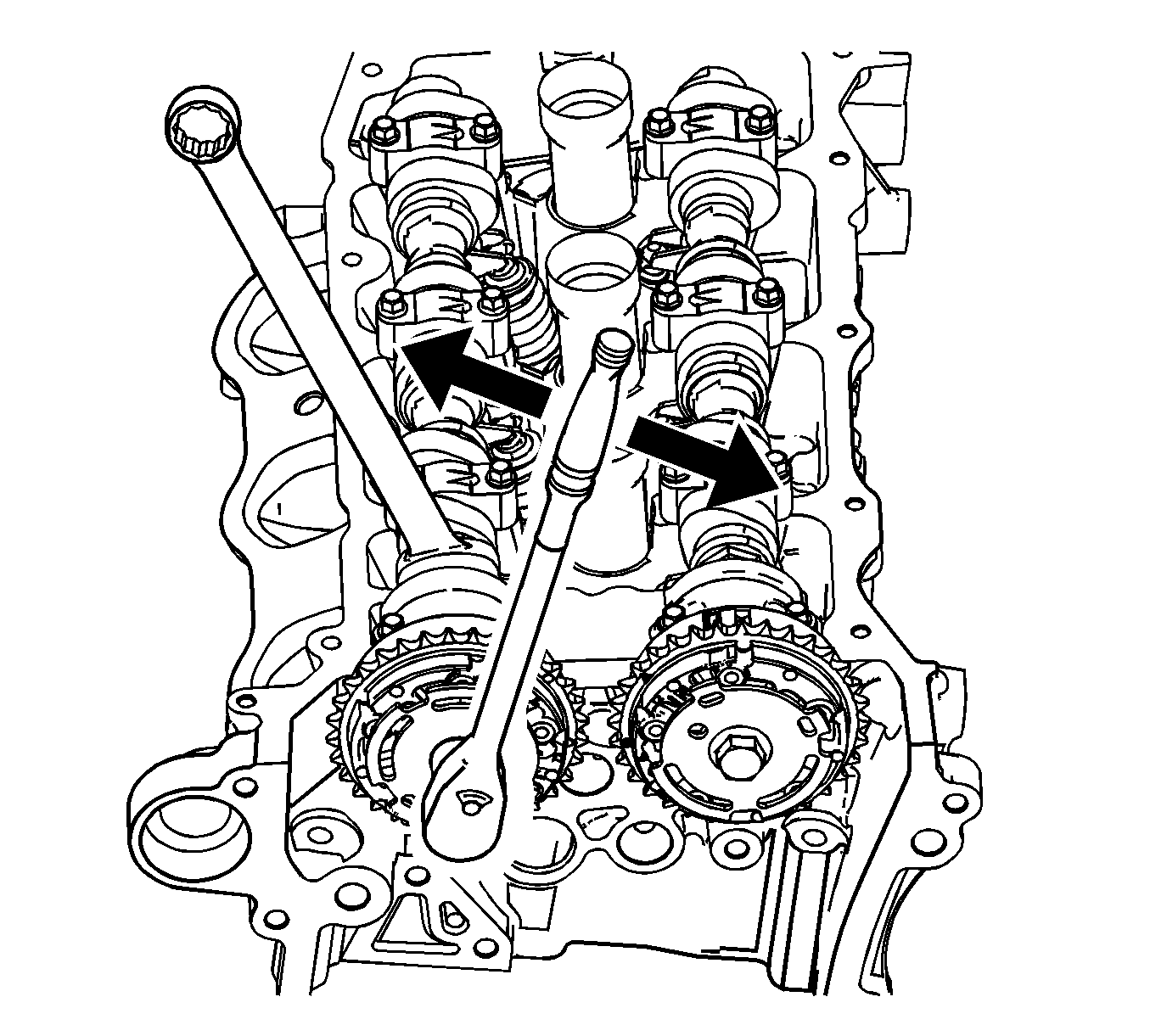
- Mark the timing chain and the respective locations on the camshaft position actuators (1-4).
- Remove the camshaft position actuator bolt.
- Remove the camshafts. Refer to Camshaft Removal - Left Side.
Notice: Refer to Torque Reaction Against Timing Drive Chain Notice in the Preface section.
Important:
• Use an open-end wrench at the camshaft hex to prevent camshaft/engine rotation. • DO NOT remove the camshaft position actuator bolt at this time.
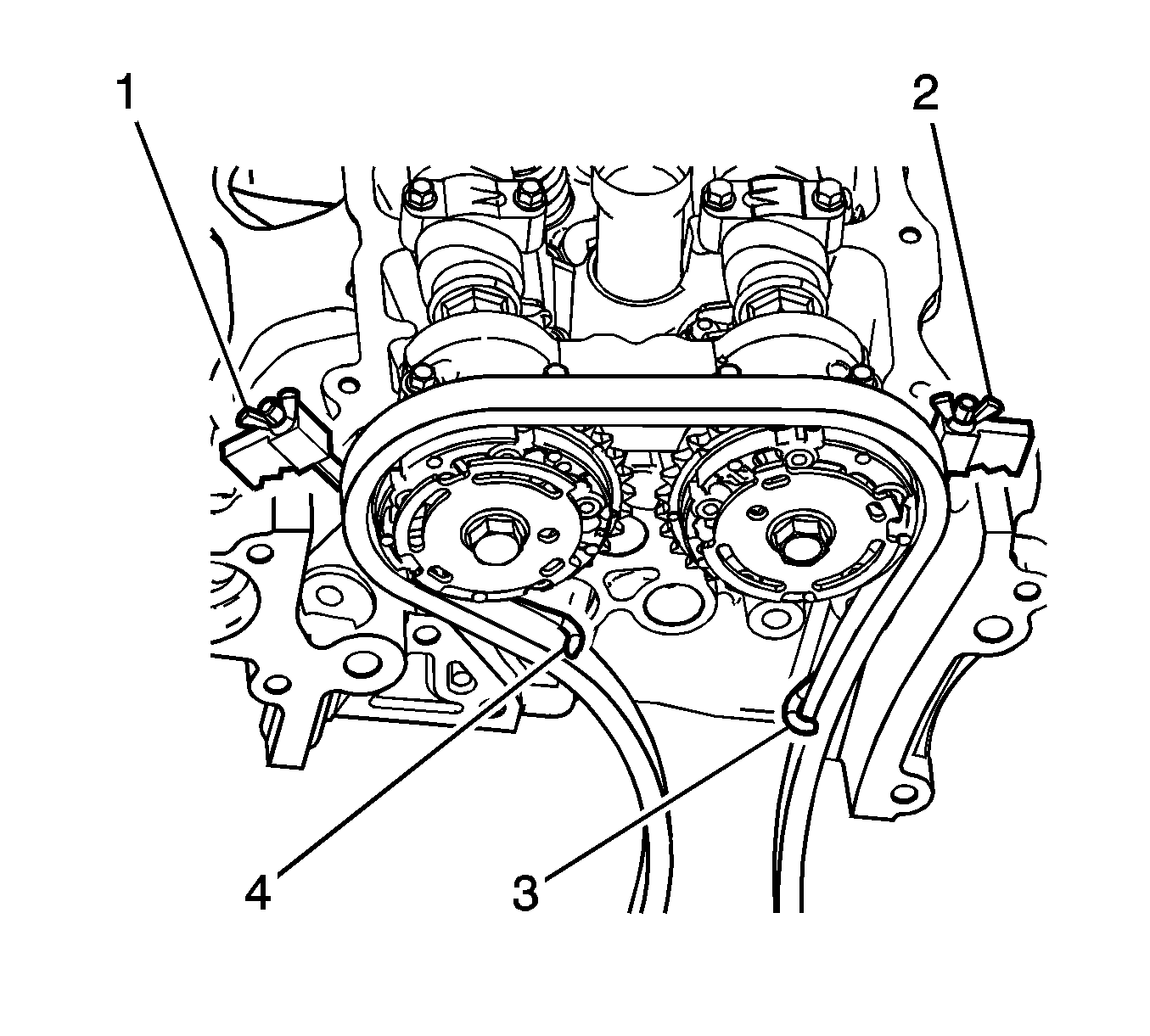
Important: Ensure that the tips of the EN 46108 are fully engaged into the timing chain (3 and 4).
Firmly tighten the EN 46108 nuts.
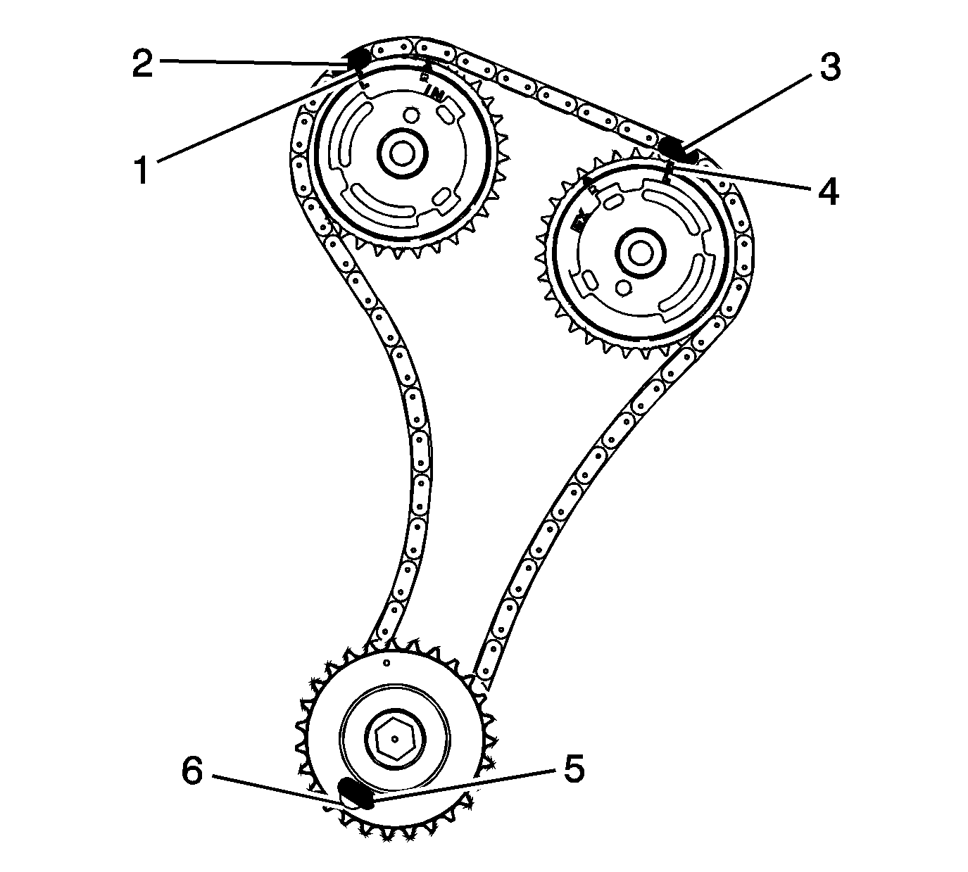
Important: Ensure that the camshaft timing chain and the camshaft position actuators are marked for proper assembly.
Installation Procedure
- Locate the camshafts to the cylinder head and assemble the camshaft actuators to the camshafts.
- Install the camshafts and the camshaft bearing caps. Refer to Camshaft Installation - Left Side.
- Remove the EN 46108 .
- Install and tighten the camshaft position actuators. Refer to Camshaft Position Actuator Installation - Left Side Intake and Camshaft Position Actuator Installation - Left Side Exhaust.
- Install the intake camshaft position actuator solenoid. Refer to Camshaft Position Actuator Solenoid Valve Solenoid Replacement - Bank 2 (Left Side) Intake.
- Install the camshaft sensors. Refer to Camshaft Position Sensor Replacement - Bank 2 (Left Side) Exhaust and Camshaft Position Sensor Replacement - Bank 2 (Left Side) Intake.
- Install the crankshaft balancer. Refer to Crankshaft Balancer Removal.
- Install the camshaft cover. Refer to Camshaft Cover Replacement - Left Side.
- Install the upper intake manifold with the lower intake manifold. Refer to Lower Intake Manifold Replacement.
Important:
• Ensure that the marks on the camshaft position actuator and the timing chain (1-4) are aligned. • DO NOT tighten the camshaft position actuator bolt at this time.
Notice: Refer to Torque Reaction Against Timing Drive Chain Notice in the Preface section.
Important: Use an open-end wrench at the camshaft hex to prevent camshaft/engine rotation.
