HIGH SHIFT EFFORT OUT OF PARK LOCKED IN PARK (ADJUST BTSI)

SUBJECT: HIGH SHIFT EFFORT OUT OF PARK/LOCKED IN PARK (INFORM CUSTOMER OF BRAKE-TRANS SHIFT PROC./ADJUST BTSI)
VEHICLES AFFECTED: 1991 C, H, W/4T60,4T60E
BULLETIN COVERS:
A vehicle equipped with a HYDRA-MATIC 4T60 or 4T60-E may exhibit high shift effort when the customer is trying to shift the transaxle out of the Park range. This could be caused by the customer not following the proper shifting procedure for the brake-transaxle shift interlock (BTSI) system. The BTSI system is designed to prevent the vehicle from being shifted out of Park unless the brake pedal is fully depressed BEFORE the shift lever is moved. When the brake pedal is depressed, the BTSI solenoid is de-energized, allowing the shift lever to be moved out of the Park range (provided that the shift lever is all the way in Park).
Customers may comment that their vehicle requires a high shift effort to shift out of Park. This is usually caused by the customer FIRST moving the shift lever, then depressing the brake pedal or trying to do both simultaneously. This will cause the interlock system to function as intended and hold the shift lever in the Park range until the shift lever is moved back fully into the Park range. Floor shift console models must have the button on the shift lever fully released before it is depressed again to disengage the interlock.
Proper shifting procedure to be communicated to the customer:
Ensure the shift lever is fully in the Park range before starting the engine. Your vehicle has a brake-transaxle shift interlock. You have to fully apply your regular brakes before you can shift from Park when the ignition key is in the "Run" or "On" position. If you cannot shift out of Park, ease pressure on the shift lever (push the shift lever all the way into Park and also release the shift lever button on floor shift console models) as you maintain brake application.
Then move the shift lever into the gear you wish (provided floor shift console models have the shift lever button depressed again).
SERVICE PROCEDURE:
Test the BTSI system and if "OK", inform the customer of the proper shifting procedure. If adjustment is needed to allow the BTSI solenoid to interlock, follow the procedure listed in "ON VEHICLE ADJUSTMENT PROCEDURE FOR COLUMN BTSI SYSTEM" or the Service Manual. Only the column shift lever system is adjustable. The floor shift console models use a system that does not have an adjustment. The column mounted shift lever models have the BTSI solenoid location on the steering column, while floor shift console models have the solenoid located in the console.
SERVICE MANUAL REFERENCE:
Refer to the Steering Column Unit Repair section 3F4 for column shift models and Automatic Transaxle On-Vehicle Service section 7A for floor shifter models in the appropriate 1991 Service Manual.
ON-VEHICLE ADJUSTMENT PROCEDURE FOR COLUMN BTSI SYSTEM:
With the steering column in the vehicle, use the following procedure to adjust the BTSI system interlock.
Verify that the shift cable is installed with no tension on the steering column shift tube lever.
1. Place the ignition lock cylinder in "OFF" position.
2. Place the shift lever in "Neutral" position.
3. Unlock the shift cable to eliminate any tension in the shift cable at the transaxle shift arm.
4. Push the lock for the shift cable back down to lock the cable.
5. Return the shift lever to "Park" position.
6. Check shift indicator for proper adjustment. If adjustment is required, refer to the Service Manual section 3F4, Shift Indicator Adjustment.
7. Check the neutral start switch for proper operation. If adjustment is required, refer to Service Manual 7A, Shift Control Cable, to adjust the shift cable.
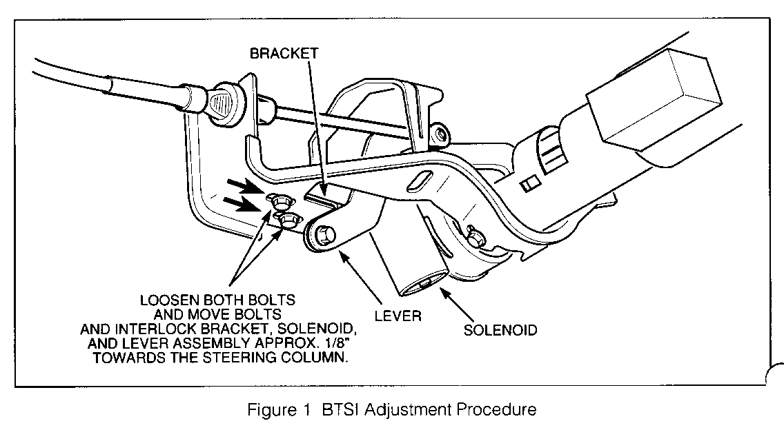
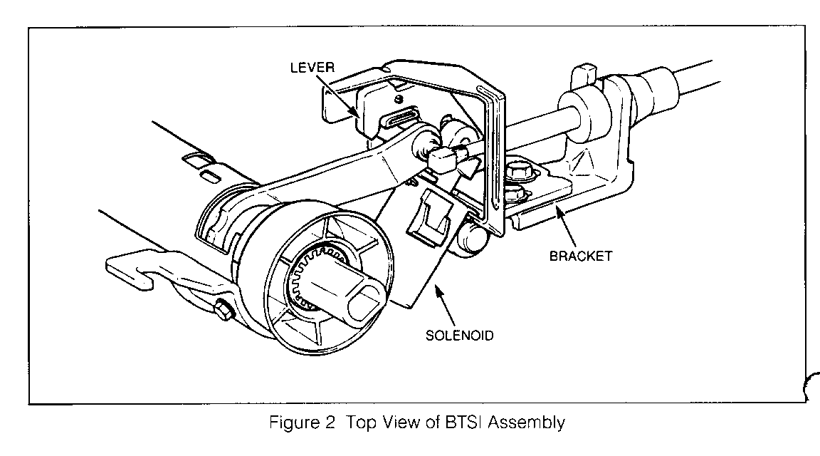
Check the BTSI system for proper operation. If condition still exists, proceed to next step, as shown in Figs. 1 and 2.
8. Change the position of the BTSI lever to the s ft tube lever pin.
9. Loosen the bolts to the interlock and solenoid :ssembly through the steering column lower support bracket.
10. Move the interlock and solenoid assembly toward the steering column approximately 2mm (1/8").
11. Tighten the bolts for the interlock and solenoid assembly evenly to 16.0 N.m (12 ft.lbs.).
Check the BTSI system for proper operation. If condition still exists, repeat steps 8 through 11.
If the condition still exists after several attempts to adjust the BTSI system, it may be necessary to remove the steering column from the vehicle to adjust the BTSI system on a bench. Refer to Service Manual section 3F4, Steering Column Unit Repair.


General Motors bulletins are intended for use by professional technicians, not a "do-it-yourselfer". They are written to inform those technicians of conditions that may occur on some vehicles, or to provide information that could assist in the proper service of a vehicle. Properly trained technicians have the equipment, tools, safety instructions and know-how to do a job properly and safely. If a condition is described, do not assume that the bulletin applies to your vehicle, or that your vehicle will have that condition. See a General Motors dealer servicing your brand of General Motors vehicle for information on whether your vehicle may benefit from the information.
