INFORMATION ON ELECT. CLIMATE CONTROL (MICROPROCESSOR)

SUBJECT: INFORMATION CONCERNING ELECTRONIC CLIMATE CONTROL (C68)
VEHICLES AFFECTED: 1991 OLDSMOBILE 98
The C68 Electronic Climate Control system is a new electronic package for 1991 and does not compare to the 1990 operating characteristics. The new system consists of the microprocessor which is located in the HVAC programmer and not the control head as in 1990. This is known as the "Smart" programmer. This system consists of the following:
- Heater and A/C control assembly (control head) - In-vehicle sensor - located in centre of dash below the radio. - Ambient temperature sensor - located on the radiator core support. - Sun load sensor - located in centre top of the I/P. - English/metric switch - located on the instrument cluster. - Low refrigerant input (pressure cycling switch) - located in the low pressure A/C line. - A/C request line - Powertrain Control Module (PCM) input. - Brushless, Pulse Width Modulated (PWM) air mix valve motor - located in the programmer. - Blower Control Module - located under the hood in the heater and A/C blower assembly. - Blower motor feedback circuit. - Serial communication line. - Entertainment and Climate Control (E&C) data communication line between the programmer and the heater and A/C control assembly.
All of the electronic devices required to operate the C68 system, as well as other electronic devices interface through the serial communication line. These devices include Retained Accessory Control (RAC) module, Powertrain Control Module (PCM), Diagnostic Energy Reserve Module (DERM), instrument cluster and HVAC microprocessor. Serial data is transmitted at 8,192 baud. The PCM is the master communication device.
The heater and A/C control assembly provides all keyboard information to the microprocessor and receives all information for display from the microprocessor.
PROGRAMMER:
----------- The microprocessor (located within the programmer) receives electrical input signals and converts them to electrical output signals. These output signals operate the HVAC mode valves (solenoid controlled vacuum actuators), air mix valve (PWM motor), blower motor speed (blower control module) and the A/C compressor clutch (A/C request input to PCM).
Vacuum is constantly applied to a programmer check valve which distributes the vacuum to four solenoid-controlled valves. Mode changes from the heater and A/C control assembly are converted to solenoid output signals by the microprocessor. The associated solenoid is energized and vacuum is applied to a vacuum actuator. The actuator, in turn, repositions its air distribution valve.
The programmer utilizes a DC bi-directional PWM motor to operate the air mix valve. As the motor turns, it moves a plastic crank arm connected to the air mix valve and regulates evaporate discharge air through or around the heater core. Attached to the air mix valve motor is a feedback potentiometer. It provides an input signal to the microprocessor regarding the air mix valve position.
If the programmer must be tested, keep it in a vertical position to enable gravity to close off all vacuum supply through the solenoids that are not energized. The only replaceable part on the programmer is the air mix motor. The only adjustment on the programmer is the temperature (air mix) valve link. The adjustment procedure can be found on Page 1C-6 of the 1991 Ninety-Eight Service Manual.
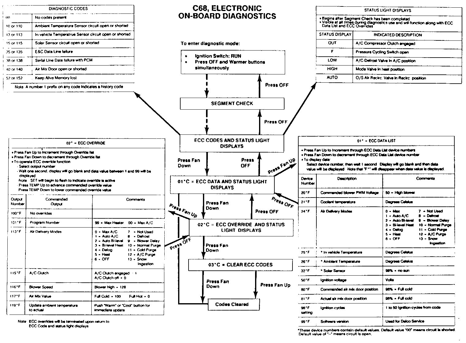
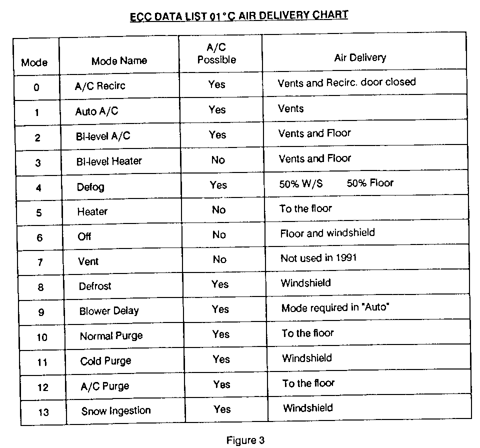
Programmer operation can be controlled and monitored through HVAC on-board diagnostics in 02 degrees C (ECC Overrides and Status light display). Chart 3 shows air delivery and mode numbers for actual air delivery into the vehicle.
IN-VEHICLE SENSOR:
The in-vehicle sensor is located in the I/P trim pad assembly and is connected by an aspirator hose to the A/C and heater module assembly. The in-vehicle sensor is a variable resistance sensor (thermistor) which is fed 5.0 volts from the HVAC microprocessor.
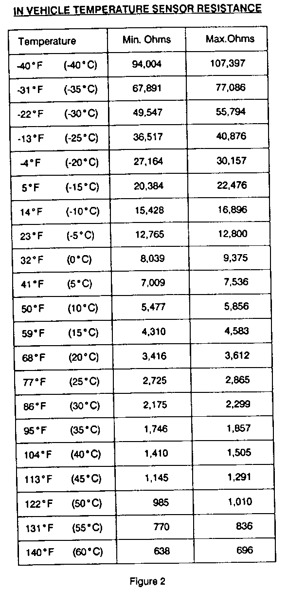
The resistance varies inversely to the temperature (low temperature high resistance and vice versa). The resistance value at a given temperature determines the signal level or degrees sent to the microprocessor. Chart 2 shows the in-vehicle sensor resistance values.
AMBIENT TEMPERATURE SENSOR
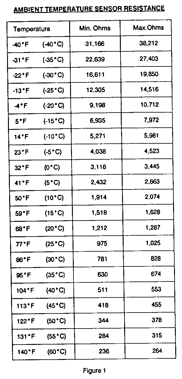
The Ambient Temperature Sensor (ATS) is located on the radiator core support and is a sealed unit. The ATS is a variable resistance sensor (thermistor) which is fed 5.0 volts from the HVAC microprocessor. The circuit has a temperature range of -40 degrees F to 199 degrees F (40 degrees C to 60 degrees C). The resistance varies inversely to the ambient temperature. The resistance at a given temperature determines the signal level or degrees sent to the microprocessor. See Chart 1 for ATS resistance values.
The ATS will not allow the A/C clutch to operate below 47 degrees F (8 degrees C). Also, the ATS input is filtered. This means certain inputs such as VSS and time must be met before ATS inputs will update. System design prohibits the ambient temperature sensor from updating until 5 hours have elapsed after the ignition is turned off. The vehicle must be driven above 10 mph before the ATS will begin to update. When diagnosing the C68 system, the ATS reading can be updated through ECC diagnostic Overrides (02 degrees C) output number 119 degrees F (reference C68 On-board diagnostics chart).
SUNLOAD SENSOR
The sunload sensor is located in the centre of the I/P under the defroster grill. This sensor detects the heat load of the sun on the vehicle. It is a photodiode with parallel resistance that is fed 5.0 volts from the HVAC microprocessor. The resistance varies inversely to light intensity. The resistance value at a given light intensity determines the signal level or degrees sent to the microprocessor. To keep the interior comfortable, the sunload sensor reduces interior temperature by as much as 5 degrees F below the setting on the heater and A/C control assembly.
ENGLISH/METRIC SWITCH ---------------------- This is a digital input switch to ground. A closed switch will cause the circuit to have low resistance thus changing the logic on the control head to Metric. When the switch is open, resistance is high and the control head will display in English. This switch is located on the I/P cluster.
LOW REFRIGERANT INPUT (Pressure Cycling Switch)
This is a digital input to the PCM and HVAC microprocessor that opens below 25 psi. If the refrigerant pressure is low and the A/C request signal causes the PCM to cycle the compressor too often, the PCM protects the compressor by disabling the A/C relay and storing a code 66. Once a code 66 is set, it is also stored as a hidden code in the HVAC microprocessor and will not allow compressor operation. Both PCM and HVAC codes must be cleared to allow the system to operate the A/C compressor. A code 66 cannot be seen in the HVAC diagnostics.
A/C REQUEST LINE AT PCM ------------------------- The A/C request line is monitored by the PCM to enable the A/C clutch relay. The relay is activated based on proper refrigerant charge in the system (low refrigerant input), mode selected from the heater and A/C control assembly and sufficient pressure to close the A/C pressure cycling switch. A PCM code 66 is set when the above conditions are not met and the PCM disables the A/C compressor. Code 66 does not illuminate the "Service Engine Soon" light. Once a PCM code 66 is set it also sets a hidden code in the HVAC microprocessor. Both PCM and HVAC codes must be cleared to allow the compressor clutch to engage.
With the heater and A/C control assembly set on "AUTO" and a current PCM code 66, the A/C compressor will turn on after each ignition cycle. The compressor clutch will operate for 5 seconds and then the HVAC microprocessor will revert to the "UPPER" mode and cancel the A/C request input to the PCM.
BLOWER MOTOR FEEDBACK CIRCUIT
Blower speed is controlled by the HVAC microprocessor from temperature signal inputs and the operation mode selected by the driver. These inputs are communicated to the microprocessor from the heater and A/C control assembly and steering wheel controls (if equipped) through the E&C data line. The output signal from the microprocessor is transmitted to the Blower Control Module. An amplifier and driver circuit in the module supply a voltage of between 4-12 volts to the blower motor.
The voltage at the blower motor is fed back to the HVAC micro- processor allowing for precise speed control of the blower motor. This feedback circuit is protected by a fuse. If the fuse is missing or blown the blower motor will operate on high speed only.
ON BOARD DIAGNOSTICS
The 1991 Ninety-Eight C68 system is equipped with an on-board diagnostic system which is accessed through the HVAC control head. The system displays fault codes, system data parameters and clears HVAC codes. It will also control output commands to the HVAC programmer. When a code is set, the temperature digits and degree symbol will flash during the first two minutes of operation. Pressing the "AUTO" button at any time terminates the diagnostic mode.
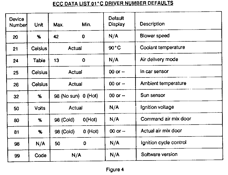
Included in this issue is a revised one page C68 Electronic On-Board Diagnostic flow chart. Also included (Charts 3 and 4) is the ECC Data List (01 degree C) Air Delivery chart and the ECC Data (01 degrees C) Device Driver Number Defaults. Service manual air conditioning wiring schematics and system checks can be found in Sections 8A-62-0 through 8A-68-19.
It is important to clear all PCM and HVAC codes after diagnosing to allow proper HVAC operation. Failure to clear all codes may result in no A/C compressor clutch operation.
AMBIENT TEMPERATURE SENSOR RESISTANCE (Chart 1) ================================================
Temperature Min. Ohms Max.Ohms --------------- ---------- ---------- -40 F (-40 C) 31,166 38,212
-31 F (-35 C) 22,639 27,403
-22 F (-30 C) 16,611 19,850
-13 F (-25 C) 12,305 14,516
-4 F (-20 C) 9,198 10,712
5 F (-15 C) 6,935 7,972
14 F (-10 C) 5,271 5,981
23 F (-5 C) 4,038 4,523
32 F (0 C) 3,116 3,445
41 F (5 C) 2,432 2,663
50 F (10 C) 1,914 2,074
59 F (15 C) 1,518 1,628
68 F (20 C) 1,212 1,287
77 F (25 C) 975 1,025
86 F (30 C) 781 828
96 F (35 C) 630 674
104 F (40 C) 511 553
113 F (45 C) 418 455
122 F (50 C) 344 378
131 F (55 C) 284 315
140 F (60 C) 236 264
IN VEHICLE TEMPERATURE SENSOR RESISTANCE (Chart 2) =================================================== Temperature Min. Ohms Max.Ohms -------------- --------- -------- -40 F (-40 C) 94,004 107,397
-31 F (-35 C) 67,891 77,086
-22 F (-30 C) 49,547 55,794
-13 F (-25 C) 36,517 40,876
-4 F (-20 C) 27,164 30,157
5 F (-15 C) 20,384 22.476
14 F (-10 C) 15,428 16,896
23 F (-5 C) 12,765 12,800
32 F (0 C) 8,039 9,375
41 F (5 C) 7,009 7,536
50 F (10 C) 5,477 5,856
59 F (15 C) 4,310 4,583
68 F (20 C) 3,416 3,612
77 F (25 C) 2,725 2,865
86 F (30 C) 2,175 2,299
95 F (35 C) 1,746 1,857
104 F (40 C) 1,410 1,505
113 F (45 C) 1,145 1,291
122 F (50 C) 985 1,010
131 F (55 C) 770 836
140 F (60 C) 638 696
ECC DATA LIST 01 DEGREES CELSIUS AIR DELIVERY CHART (Chart 3) ============================================================= A/C Mode Mode Name Possible Air Delivery ----- ---------- -------- ----------------------------- 0 A/C Recirc Yes Vents and Recirc. door closed
1 Auto A/C Yes Vents
2 Bilevel A/C Yes Vents and Floor
3 Bilevel Heater No Vents and Floor
4 Defog Yes 50% W/S 50% Floor
5 Heater No To the floor
6 Off No Floor and windshield
7 Vent No Not used in 1991
8 Defrost Yes Windshield
9 Blower Delay Yes Mode required in "Auto"
10 Normal Purge Yes To the floor
11 Cold Purge Yes Windshield
12 A/C Purge Yes To the floor
13 Snow Ingestion Yes Windshield
ECC DATA LIST 01 DEGREES C DRIVER NUMBER DEFAULTS (Chart 4) ============================================================ | | | | Device | | | Default | Number | Unit | Max. Min. | Display | Description | | | | 20 | % | 42 0 | N/A | Blower speed --------------------------------------------------------------------- 21 | Celsius | Actual | 90 C | Coolant temperature --------------------------------------------------------------------- 24 | Table | 13 0 | N/A | Air delivery mode --------------------------------------------------------------------- 25 | Celsius | Actual | 00 or- | In car sensor --------------------------------------------------------------------- 26 | Celsius | Actual | 00 or- | Ambient temperature --------------------------------------------------------------------- 32 | % | 98 (No sun)0(Hot)| 00 or- | Sun sensor --------------------------------------------------------------------- 50 | Volts | Actual | N/A | ignition voltage --------------------------------------------------------------------- 80 | % | 98 (Cold) 0(Hot)| N/A | Command air mix door --------------------------------------------------------------------- 81 | % | 98 (Cold) 0(Hot)| 00 or- | Actual air mix door --------------------------------------------------------------------- 98 | N/A | 50 0 | N/A | Ignition cycle control --------------------------------------------------------------------- 99 | Code | N/A | N/A | Software version | | | |
General Motors bulletins are intended for use by professional technicians, not a "do-it-yourselfer". They are written to inform those technicians of conditions that may occur on some vehicles, or to provide information that could assist in the proper service of a vehicle. Properly trained technicians have the equipment, tools, safety instructions and know-how to do a job properly and safely. If a condition is described, do not assume that the bulletin applies to your vehicle, or that your vehicle will have that condition. See a General Motors dealer servicing your brand of General Motors vehicle for information on whether your vehicle may benefit from the information.
