89 TEVES ABS HYDRAULIC UNIT SERVICE PROCEDURE

MODELS AFFECTED: 1988 DE VILLES AND FLEETWOODS
All 1988 DeVilles and Fleetwoods built after VIN breakpoint 349698 were built using 1989 Teves ABS hydraulic units which were pulled ahead for 1988 production.
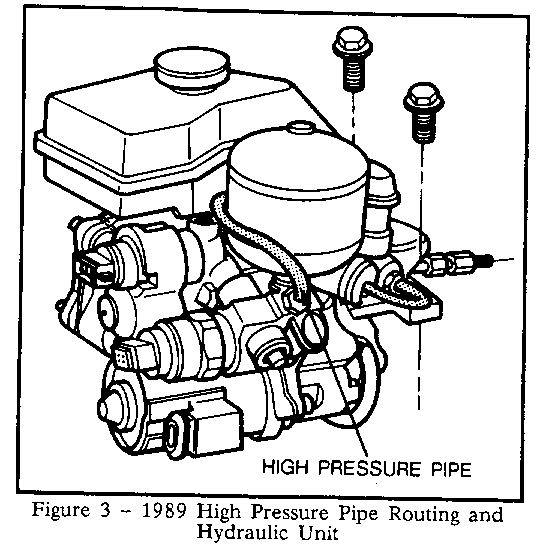
The 1988 and 1989 Teves ABS hydraulic units are identical in appearance and function, with the exception of the high pressure hose and banjo bolts which have been replaced by a steel pipe and appropriate fittings. The routing of the steel pipe now goes behind the accumulator instead of the high pressure hose's old route in front of the accumulator.
All service procedures for the 1989 hydraulic unit are the same as those for the 1988 hydraulic unit with the exceptions of the pump/motor assembly removal and installation and the installation of the pressure gage. In the event that the services mentioned above are needed, use the procedures outlined in this bulletin or the 1989 DeVille/Fleetwood Service Information Manual.
J-35604 Pressure Gage and Adapter
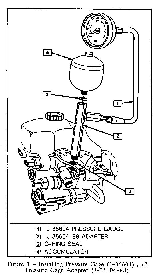
Some diagnostic procedures require that the J-35604 pressure gage and J-35604-88 pressure gage adapter be installed on the hydraulic unit in order to measure accumulator pressure during various phases of operation. The pressure gage and adapter may be installed on the Teves hydraulic unit as described in the following procedure:
1. With ignition off, pump the brake pedal a minimum of 25 times using approximately 50 lbs. (222N) pedal force. A noticeable change in pedal feel will occur when the accumulator is discharged.
2. When a definite increase in pedal effort is felt, pump pedal a few additional times. This should remove all hydraulic pressure from the system.
CAUTION:
Failure to depressurize hydraulic accumulator prior to performing this operation may result in personal injury and/or damage to painted surfaces.
3. Remove the hydraulic accumulator and 0-ring seal.
4. Install the hydraulic accumulator and 0-ring seal to the J-35604-88 pressure gage adapter.
5. Install the J-35604-88 pressure gage adapter to the pump and motor assembly. Make sure an 0-ring seal is used when attaching the adapter to the pump and motor assembly. Tighten to 40 N-m (32 ft. lbs.), refer to Figure 1.
6. Install the second 0-ring seal on the J-35604 pressure gage fitting and thread the gage fitting into the J-35604-88 adapter. Tighten the fitting to 20 N-m (15 ft. lbs.).
7. When removing the gage or adapter, inspect 0-ring seals for cuts or damage. Replace any cut or damaged 0-ring seals.
8. Proceed with tests as outlined in the diagnostic procedure. When removing pressure gage and adapter, be sure that the hydraulic accumulator is depressurized. It is not necessary to bleed the hydraulic unit after installation and removal of the pressure gage unless additional hydraulic pipes, hoses, or fittings were loosened or removed. See Section 5E for bleeding procedures as required.
PUMP AND MOTOR ASSEMBLY
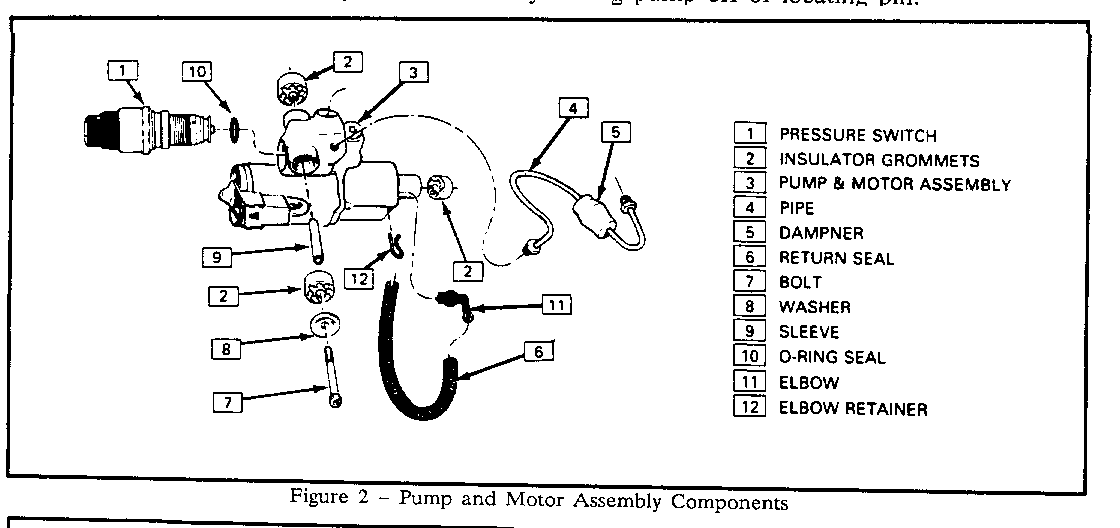
Remove or Disconnect (refer to Figures 2 and 3)
1. Turn ignition OFF or remove negative battery cable.
2. Electrical connector from pressure switch and pump motor.
CAUTION:
Failure to depressurize hydraulic accumulator prior to performing this operation may result in personal injury and/or damage to painted surfaces.
3. Depressurize hydraulic accumulator by pumping brake pedal a minimum of 25 times as described in this section.
4. Using vice grips or similar method, pinch return hose (from reservoir to pump inlet) to prevent fluid loss when hose is disconnected. Alternatively, fluid may be removed from the reservoir using a clean syringe or equivalent method.
CAUTION:
DO NOT REMOVE BRAKE FLUID FROM THE RESERVOIR USING A SYRINGE OR OTHER INSTRUMENT WHICH IS CONTAMINATED WITH WATER, PETROLEUM-BASED FLUIDS, OR ANY OTHER FOREIGN MATERIAL. CPONTAMINATION OF THE BRAKE FLUID MAY RESULT IN IMPAIRED SYSTEM OPERATION, PROPERTY DAMAGE, OR PERSONAL INJURY.
5. Hydraulic accumulator and 0-ring seal.
6. Pressure pipe assembly.
7. Wire clip which retains return hose at pump body. Pull return hose fitting out of pump body.
8. Pump mounting bolt, sleeve and insulator.
9. Pump and motor assembly from vehicle by sliding pump off of locating pin.
Inspect
o Pump monitoring insulators and replace if damaged or deteriorated.
Install or Connect
1. Position pump and motor assembly on booster/master cylinder.
2. Pump mounting bolt, sleeve and insulator.
3. Pressure pipe assembly at pump. Tighten fittings to 12 N-m (9 ft. lbs.).
4. Accumulator. Tighten to 40 N-m (30 ft. lbs.).
5. Return hose and fitting into pump body. Install wire clip.
6. Remove vice grips or other tools if used to pinch return hose during removal process.
7. If fluid was removed from reservoir, fill reservoir to "Full" mark.
8. Connect electrical connectors at pump motor and pressure switch.
9. Turn ignition on. "BRAKE" light should go out within 30 seconds and pump motor should turn off within 40 seconds.
Inspect
o For leakage.
For service parts use the following part numbers, all other service part numbers are carryover from 1988:
Actuator Assembly without Valve Block . . . . .. . . . 25535706 Pump/Motor Assembly with PWS . . . . . . . . . . . . . . 25535707 Insulator Bushing - Pump/Motor Assembly . . . . . . . 25535708 High Pressure Pipe . . . . . . . . . . . . . . . . . . . . 25535705


General Motors bulletins are intended for use by professional technicians, not a "do-it-yourselfer". They are written to inform those technicians of conditions that may occur on some vehicles, or to provide information that could assist in the proper service of a vehicle. Properly trained technicians have the equipment, tools, safety instructions and know-how to do a job properly and safely. If a condition is described, do not assume that the bulletin applies to your vehicle, or that your vehicle will have that condition. See a General Motors dealer servicing your brand of General Motors vehicle for information on whether your vehicle may benefit from the information.
