For 1990-2009 cars only
Upper Control Arm Replacement 1500
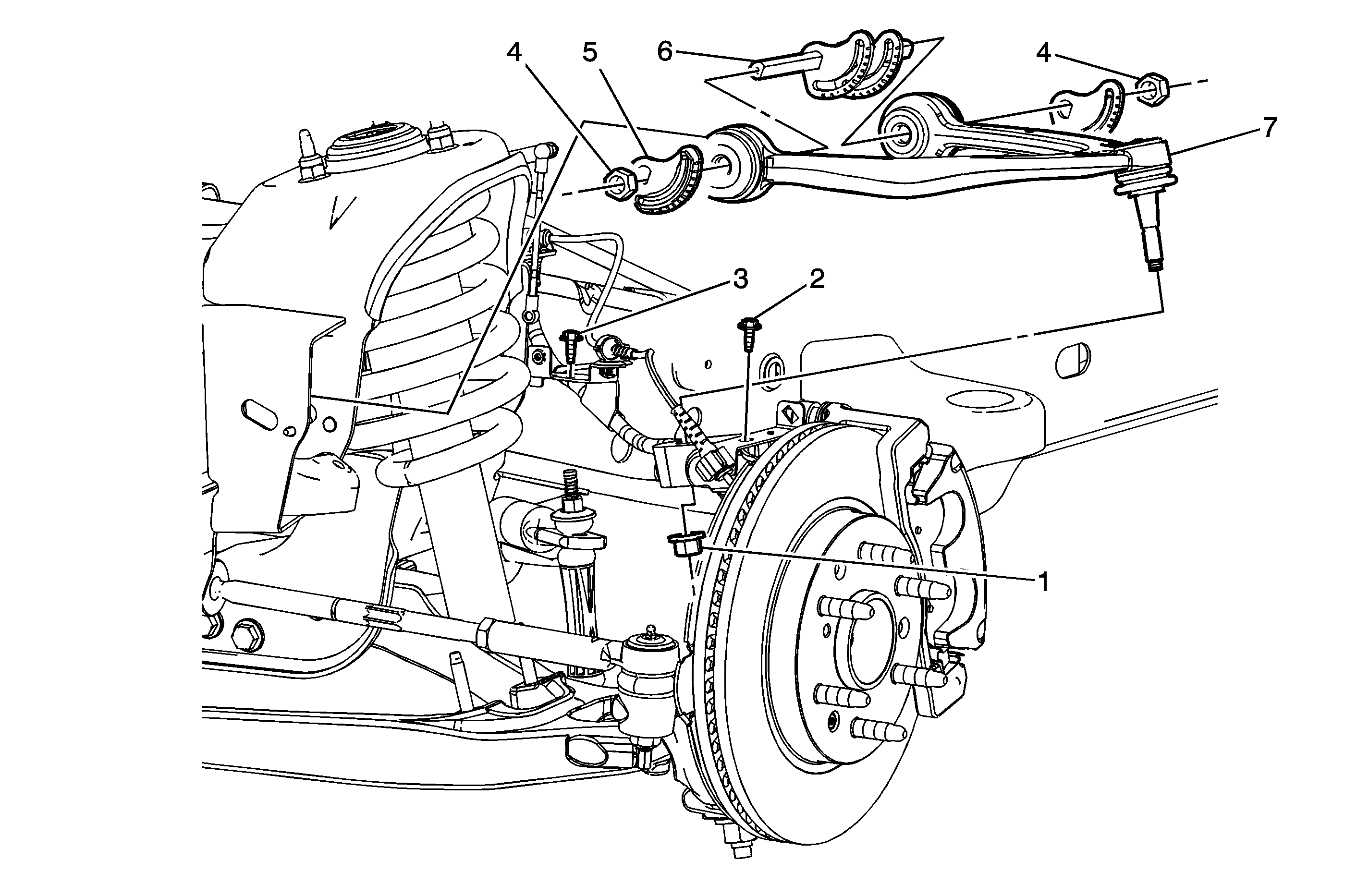
Callout | Component Name |
|---|---|
Preliminary Procedures
| |
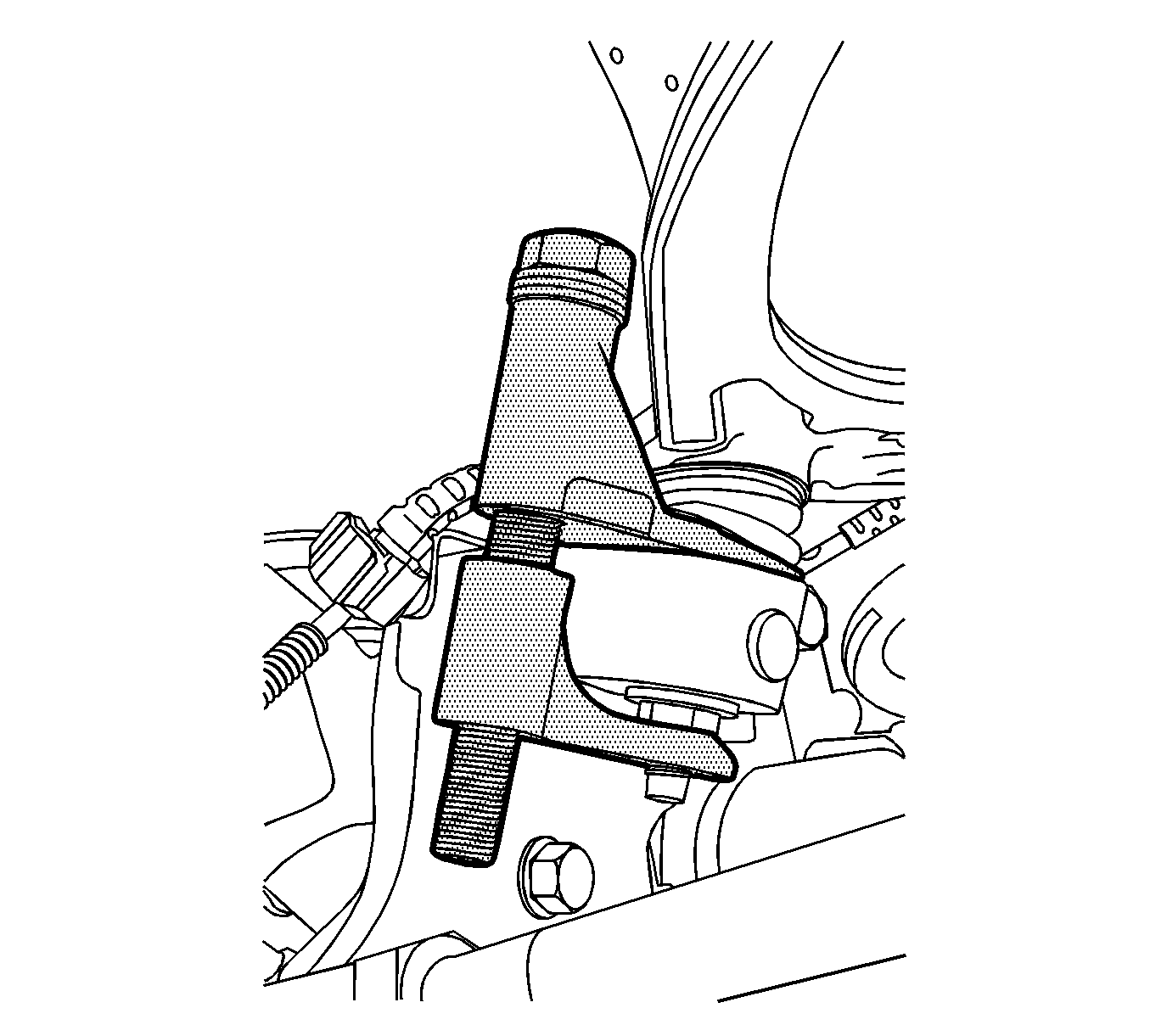
1 | Upper Ball Joint Nut Caution: Refer to Fastener Caution in the Preface section. Procedure
Tighten Special ToolsJ-42188-B Ball Joint Separator |
2 | Wheel Speed Sensor Wire Bolt Tighten |
3 | Brake Hose/Wheel Speed Sensor Harness Retainer Bolt Tighten |
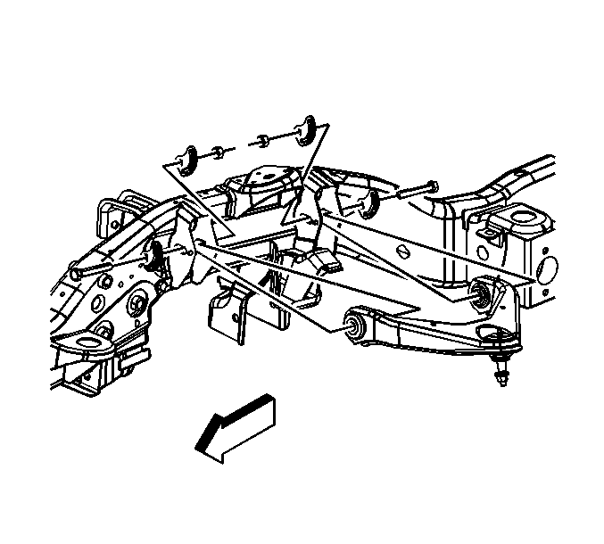
4 | Upper Control Arm Nut (Qty: 4) Tighten |
5 | Upper Control Arm Alignment Cam (Qty: 4) |
6 | Upper Control Arm Bolt (Qty: 2) |
7 | Upper Control Arm Tip |
Upper Control Arm Replacement 2500
Special Tools
J-42188-B Ball Joint Separator
Removal Procedure
- Raise and support the vehicle. Refer to Lifting and Jacking the Vehicle.
- Remove the tire and wheel. Refer to Tire and Wheel Removal and Installation.
- Remove the retaining bolt for the brake hose and the wheel speed sensor brackets.
- Remove the nut at the upper ball joint. Discard the nut.
- Disconnect the upper control arm from the steering knuckle using the J-42188-B .
- Remove the upper control arm nuts and the adjustment cams.
- Remove the upper control arm.
Installation Procedure
- Install the upper control arm.
- Install the upper control arm bolts and tighten to 190 N·m (140 lb ft).
- Connect the upper control arm to the steering knuckle.
- Install the new nut to the upper ball joint stud and tighten to 50 N·m (39 lb ft).
- Install the retaining bolts for the brake hose and wheel speed sensor brackets and tighten to 9 N·m (80 lb in).
- Install the tire and wheel. Refer to Tire and Wheel Removal and Installation.
- Lower the vehicle.
- Verify the wheel alignment. Refer to Wheel Alignment Specifications.
Caution: Refer to Fastener Caution in the Preface section.
