Differential Carrier Assembly Final Assembly 8.25 Lock Tab Style
Tools Required
| • | J 8092
Universal Driver Handle - ¾ in - 10 |
| • | J 36609
Axle Tube Bearing Installer |
| • | J 36616
Axle Mount Bushing Remover/Installer |
- Inspect the alignment mark between the differential bearing adjuster and the differential carrier assembly case. If the line between the differential bearing adjuster and the differential carrier assembly case is not aligned, re-align the 2 components
as necessary.
- Bend the differential adjuster nut lock tabs over the differential adjuster nut sleeves.
- Lubricate the clutch shaft pilot bearing with axle lubricant. Use the correct fluid. Refer to
Adhesives, Fluids, Lubricants, and Sealers
.
- Install the clutch shaft pilot bearing using the
J 33842
.
- Install the clutch shaft to the differential carrier case half.
Notice: Refer to Fastener Notice in the Preface section.
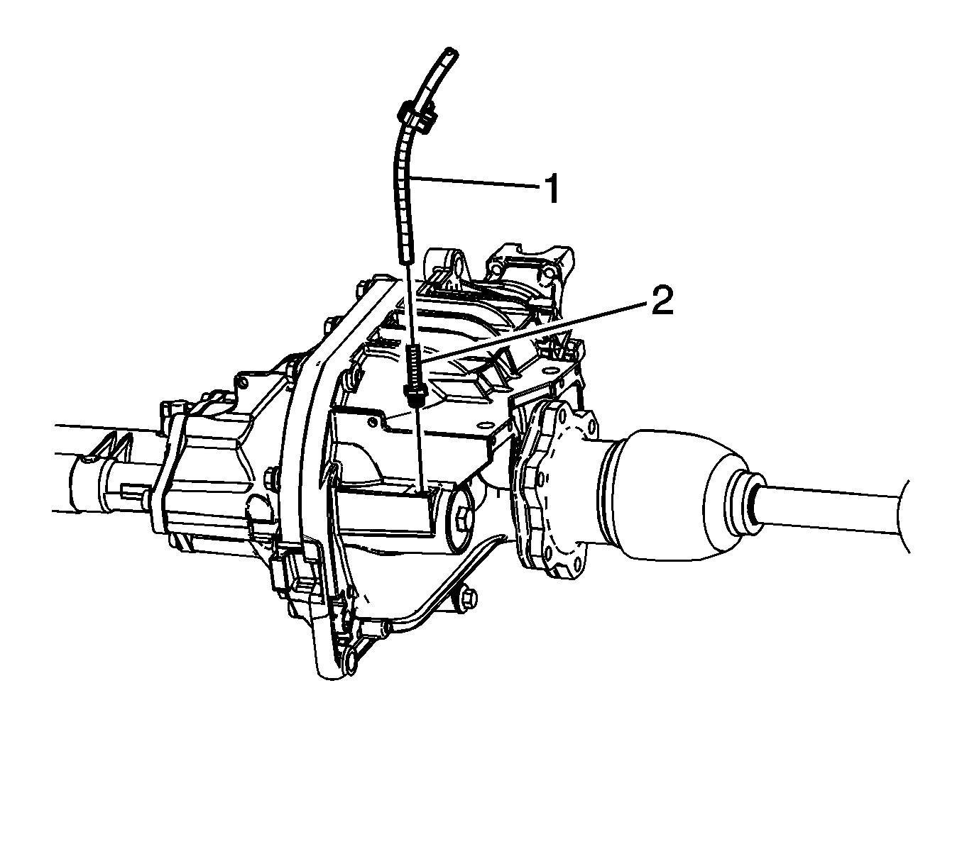
- Install the vent hose connector (2).
Tighten
Tighten the vent hose connector to 20 N·m (15 lb ft).
- Install the vent hose (1).
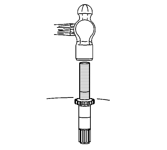
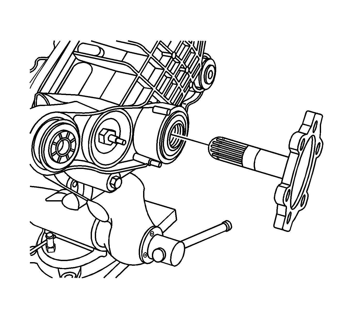
- Install the new left side axle shaft seal using the
J 45225
(1) and the
J 8092
(2).
- Install the new left side inner axle shaft retainer ring.
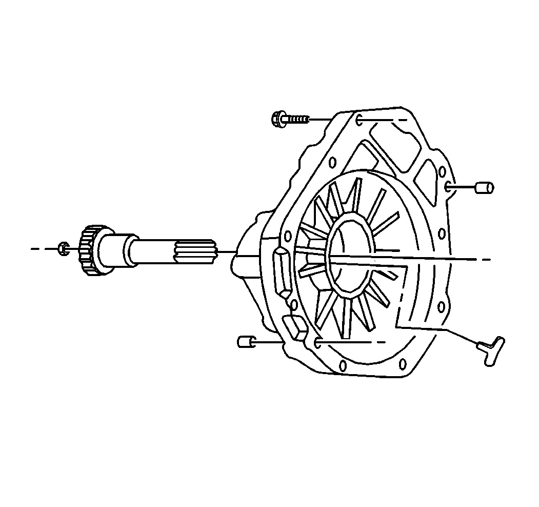
- Install the left side inner axle shaft by doing the following:
| 10.1. | Install the left side inner shaft into the differential carrier assembly until the inner shaft is seated against the differential side gear. |
| 10.2. | While holding the inner shaft against the differential side gear, turn the inner shaft in order to align the splines of the inner shaft with the splines on the differential side gear. |
| 10.3. | Drive the inner shaft into the differential case side gear using a soft-faced mallet until the retaining ring on the inner shaft is fully seated within the groove in the differential case side gear. |
Pull back on the inner shaft to ensure
that the inner shaft is properly retained in the differential case side gear.
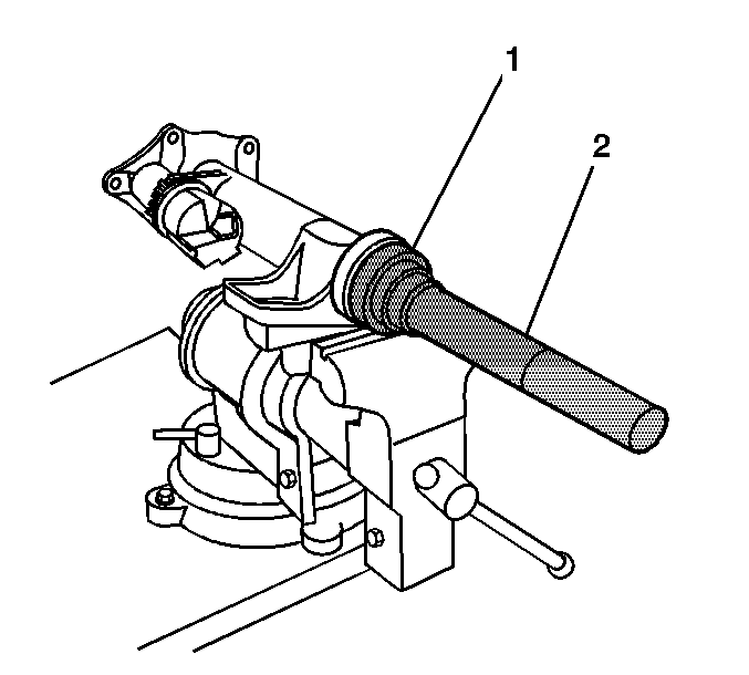
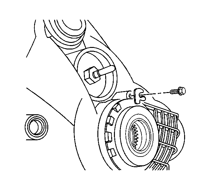
- Install the right side inner shaft bearing into the inner shaft housing by performing
the following steps:
| 11.1. | Install the inner axle shaft housing into a vise. |
Clamp only on the mounting flange of the inner axle shaft housing.
| 11.2. | Install the bearing with the square shoulder in using the
J 36609
(1) and the
J 8092
(2). |
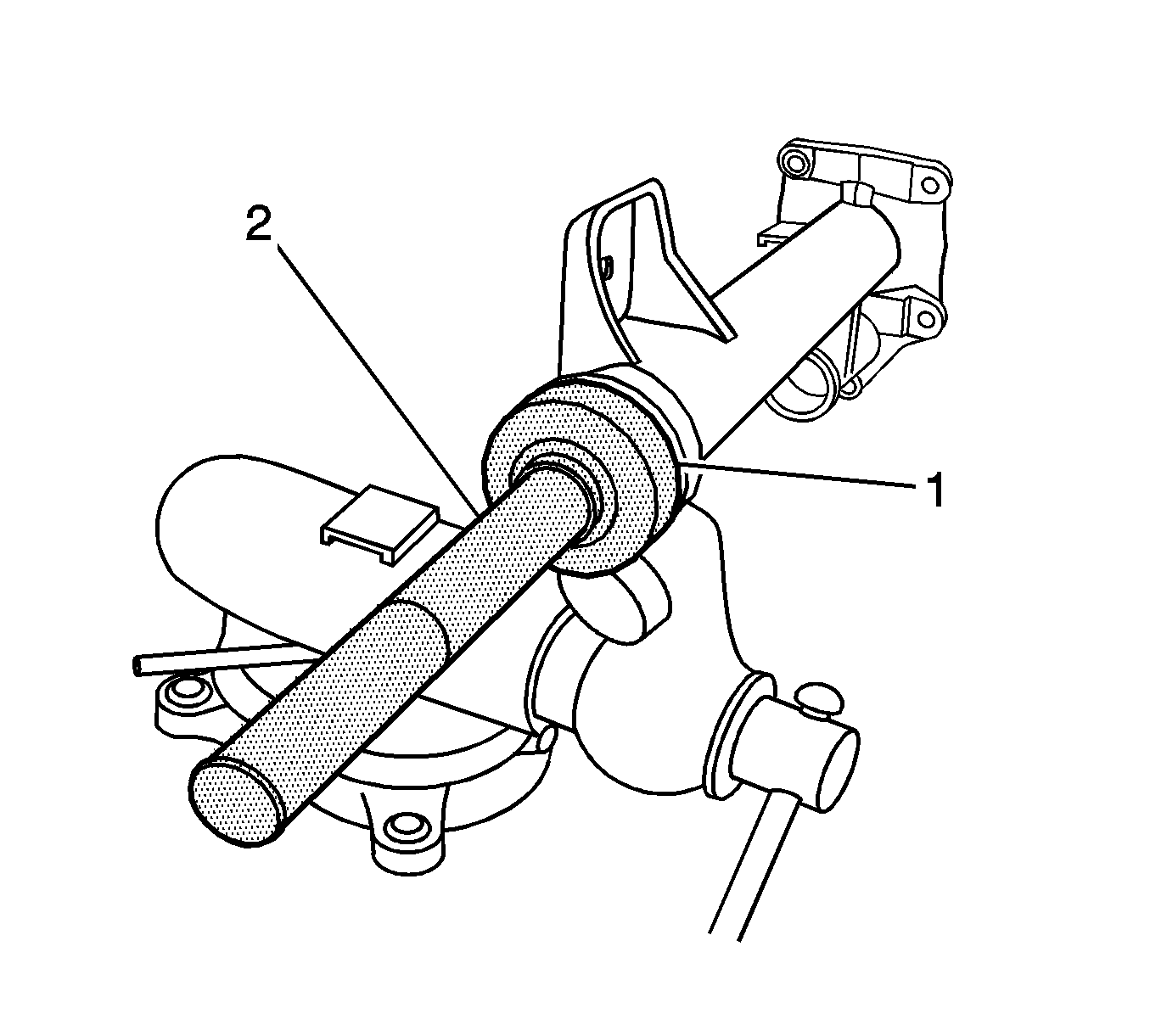
- Install the new right side inner axle shaft seal using the
J 45225
(1) and the
J 8092
(2).
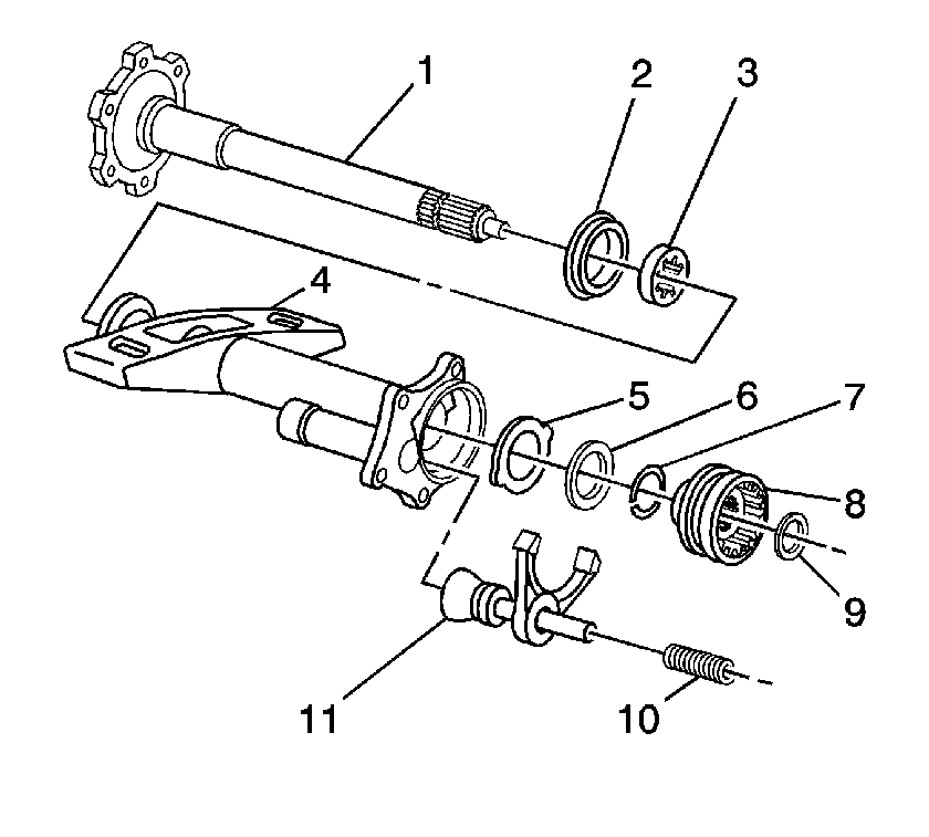
- If servicing the 8.25 (S4WD), install the following
components into the inner shaft housing:
| 13.1. | Install the inner axle shaft (1). |
Carefully tap the inner axle shaft into place with a soft-faced mallet.
| | Important: Use chassis grease in order to hold the thrust washer in place.
|
| 13.2. | Install the thrust washer (with tabs) (5). |
Ensure the tabs on the thrust washer are aligned with the slots in the inner shaft housing.
| 13.3. | Install the thrust washer (without tabs) (6). |
| 13.4. | Install the new retainer ring (7) onto the inner axle shaft (1). |
| 13.6. | Install the clutch gear shim (9). |
| 13.7. | Install the clutch sleeve (8). |
| 13.8. | Install the clutch fork assembly (11). |
| 13.9. | Install the clutch fork inner spring (10). |
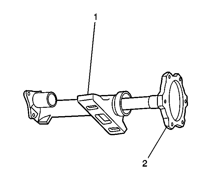
- Install the inner shaft housing to the
differential carrier assembly case. 8.25 S4WD Axle shown, 8.25 F4WD similar.
- If servicing the 8.28 inch axle, install the inner shaft housing bolts.
Tighten
Tighten the inner shaft housing bolts to 73 N·m (54 lb ft).
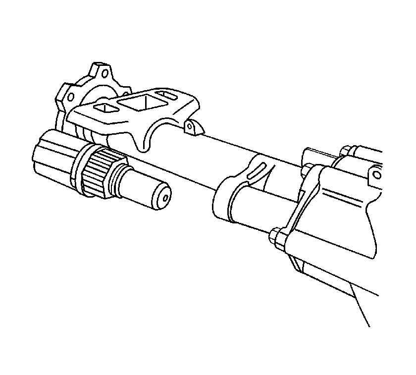
- Install the inner shaft (2) into the inner shaft housing (1) by doing the following:
| 16.1. | Install the inner shaft into the inner axle shaft housing until the inner shaft is seated against the differential side gear. |
| 16.2. | While holding the inner shaft against the differential side gear, turn the inner shaft in order to align the splines of the inner shaft with the splines on the differential side gear. |
| 16.3. | Drive the inner shaft into the differential case side gear using a soft-faced mallet until the retaining ring on the inner shaft is fully seated within the groove in the differential case side gear. |
Pull back on the inner shaft to ensure
that the inner shaft is properly retained in the differential case side gear.
- Install the drain plug and the washer.
Notice: Refer to Component Fastener Tightening Notice in the Preface section.
- Install the fill plug and the washer.
Tighten
Tighten the drain plug and the fill plug to 33 N·m (24 lb ft).
- Install the front drive axle actuator.
Apply sealant to the threads of the front axle actuator.
Use the correct sealant. Refer to
Adhesives, Fluids, Lubricants, and Sealers
.
Tighten
Tighten the front drive axle actuator to 20 N·m (15 lb ft).
Differential Carrier Assembly Final Assembly 8.25 Lock Ring Style
Tools Required
| • | J 8092 Universal Driver Handle - ¾ in - 10 |
| • | J 36609 Axle Tube Bearing Installer |
| • | J 36616 Axle Mount Bushing Remover/Installer |
- Inspect the alignment mark between the differential bearing adjuster and the differential carrier assembly case. If the line between the differential bearing adjuster and the differential carrier assembly case is not aligned, re-align the 2 components
as necessary.
- Bend the right side differential adjuster nut lock tabs over the differential adjuster nut sleeves.
- Install the differential adjuster nut lock.
Notice: Refer to Fastener Notice in the Preface section.
- Install the differential adjuster nut lock bolt.
Tighten
Tighten the differential adjuster lock nut bolt to 20 N·m (15 lb ft).
- Lubricate the clutch shaft pilot bearing with axle lubricant. Use the correct fluid. Refer to
Adhesives, Fluids, Lubricants, and Sealers .
- Install the clutch shaft pilot bearing using the
J 33842 .
- Install the clutch shaft to the differential carrier case half.
- Install the vent hose connector.
Tighten
Tighten the vent hose connector to 28 N·m (21 lb ft).
- Install the new left side axle shaft seal using the
J 45225 (1) and the
J 8092 (2).
- Install the new left side inner axle shaft retainer ring.
- Install the left side inner axle shaft by doing the following:
| 11.1. | Install the left side inner shaft into the differential carrier assembly until the inner shaft is seated against the differential side gear. |
| 11.2. | While holding the inner shaft against the differential side gear, turn the inner shaft in order to align the splines of the inner shaft with the splines on the differential side gear. |
| 11.3. | Drive the inner shaft into the differential case side gear using a soft-faced mallet until the retaining ring on the inner shaft is fully seated within the groove in the differential case side gear. |
Pull back on the inner shaft to ensure
that the inner shaft is properly retained in the differential case side gear.
- Install the right side inner shaft bearing into the inner shaft housing by performing the following steps:
| 12.1. | Install the inner axle shaft housing into a vise. |
Clamp only on the mounting flange of the inner axle shaft housing.
| 12.2. | Install the bearing with the square shoulder in using the
J 36609 (1) and the
J 8092 (2). |
- Install the new right side inner axle shaft seal using the
J 45225 (1) and the
J 8092 (2).
- Install the following components into the inner shaft housing:
| 14.1. | Install the inner axle shaft (1). |
Carefully tap the inner axle shaft into place with a soft-faced mallet.
| | Important: Use chassis grease in order to hold the thrust washer in place.
|
| 14.2. | Install the thrust washer (with tabs) (5). |
Ensure the tabs on the thrust washer are aligned with the slots in the inner shaft housing.
| 14.3. | Install the thrust washer (without tabs) (6). |
| 14.4. | Install the new retainer ring (7) onto the inner axle shaft (1). |
| 14.6. | Install the clutch gear shim (9). |
| 14.7. | Install the clutch sleeve (8). |
| 14.8. | Install the clutch fork assembly (11). |
| 14.9. | Install the clutch fork inner spring (10). |
- Apply sealant to the inner shaft housing to differential carrier sealing surface. Use the correct sealant. Refer to
Adhesives, Fluids, Lubricants, and Sealers .
- Install the inner shaft housing to the differential carrier assembly case.
- Install the inner shaft housing bolts.
Tighten
Tighten the inner shaft housing bolts to 40 N·m (30 lb ft).
- Install the drain plug and the washer.
- Install the fill plug and the washer.
Tighten
Tighten the drain plug and the fill plug to 33 N·m (24 lb ft).
Notice: Refer to Component Fastener Tightening Notice in the Preface section.
- Install the front drive axle actuator.
Apply sealant to the threads of the front axle actuator. Use the correct sealant. Refer to
Adhesives, Fluids, Lubricants, and Sealers .
Tighten
Tighten the front drive axle actuator to 20 N·m (15 lb ft).
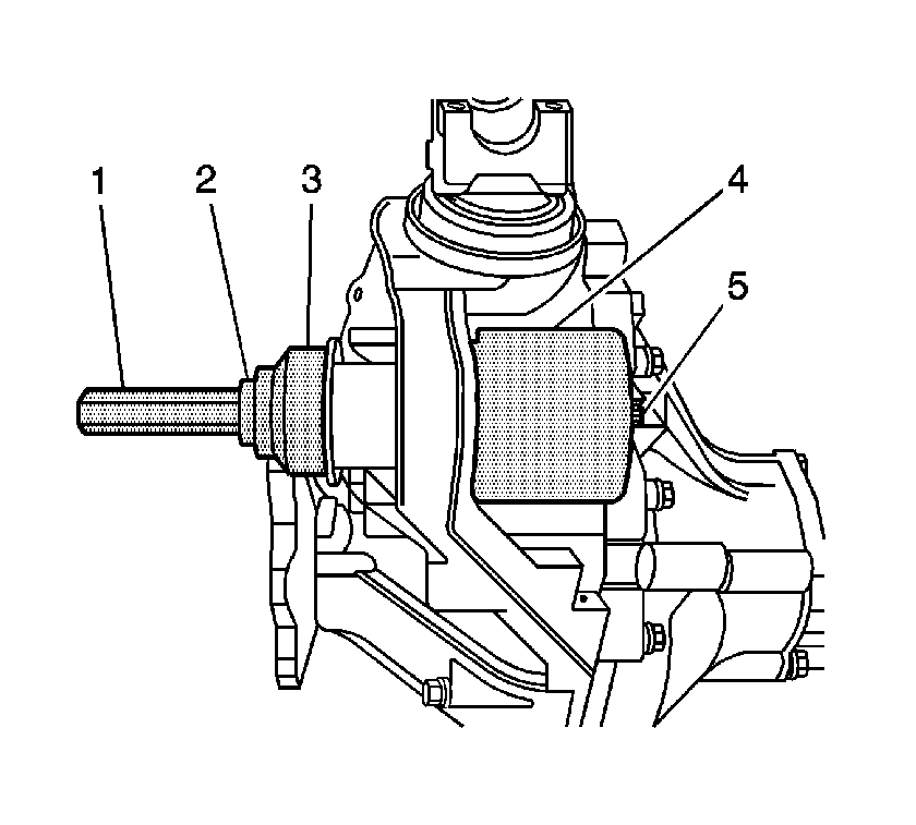
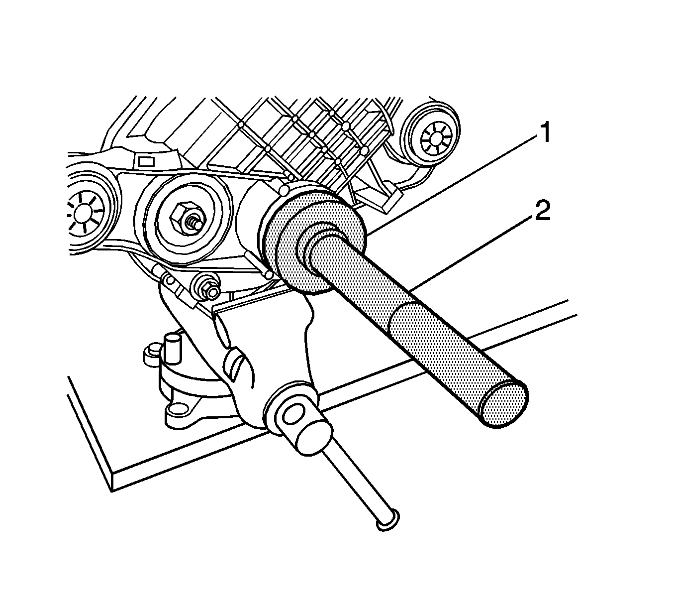
- Install the lower differential carrier assembly bushing by performing the following steps:
| 21.1. | Install the J 21474-18 (1), the thrust bearing (2), the J 36616-2 (3), the J 36616-1 (4), and the forcing screw (5) as shown. |
| 21.2. | While holding the forcing screw, slowly tighten the J 21474-18 until the bushing has stopped against the step on the bushing and is centered within the differential carrier assembly bushing bore. |
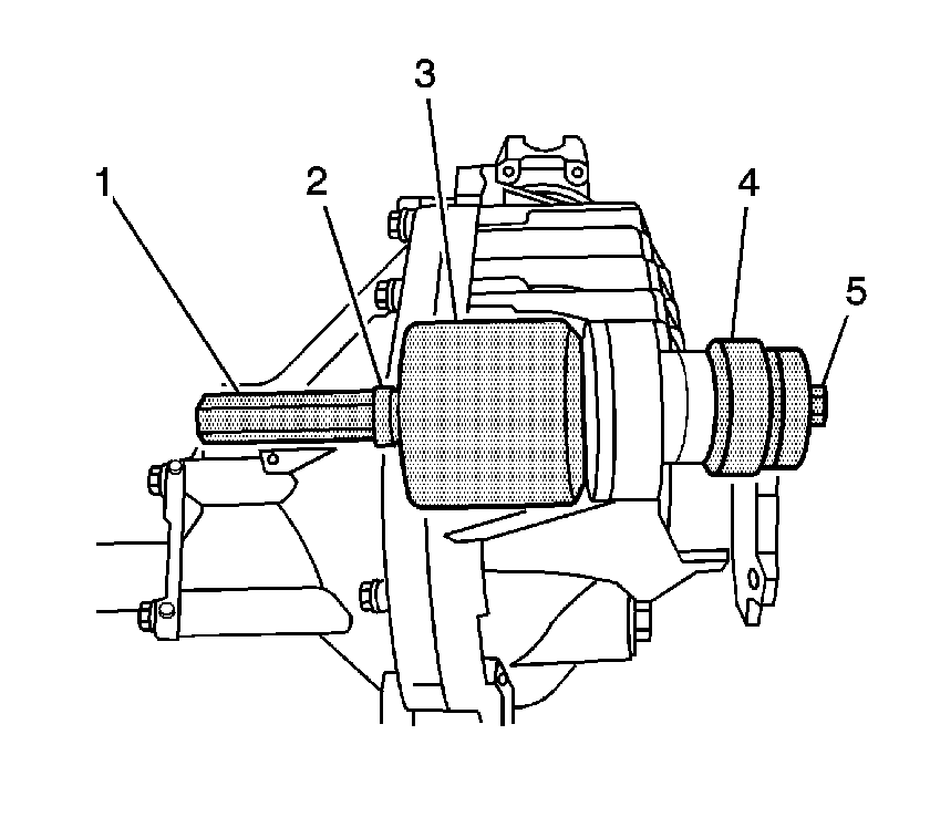
- Install the upper differential carrier assembly bushing by performing the following steps:
| 22.1. | Install the J 21474-18 (1), the thrust bearing (2), the J 36616-2 (3), the J 36616-1 (4), and the forcing screw (5) as shown. |
| 22.2. | While holding the forcing screw, slowly tighten the J 21474-18 until the bushing has stopped against the step on the bushing and is centered within the differential carrier assembly bushing bore. |
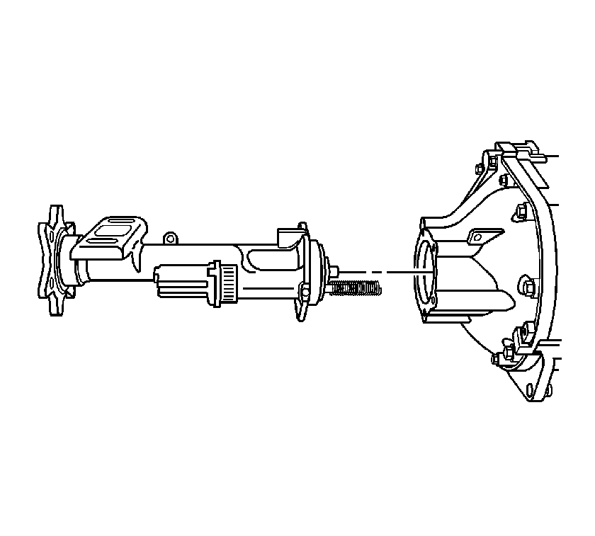
- Install the differential carrier assembly. Refer to
Differential Carrier Assembly Replacement .
