GM Service Manual Online
For 1990-2009 cars only
Figure 1:

Power, Ground, Class 2, and Front Blower Controls
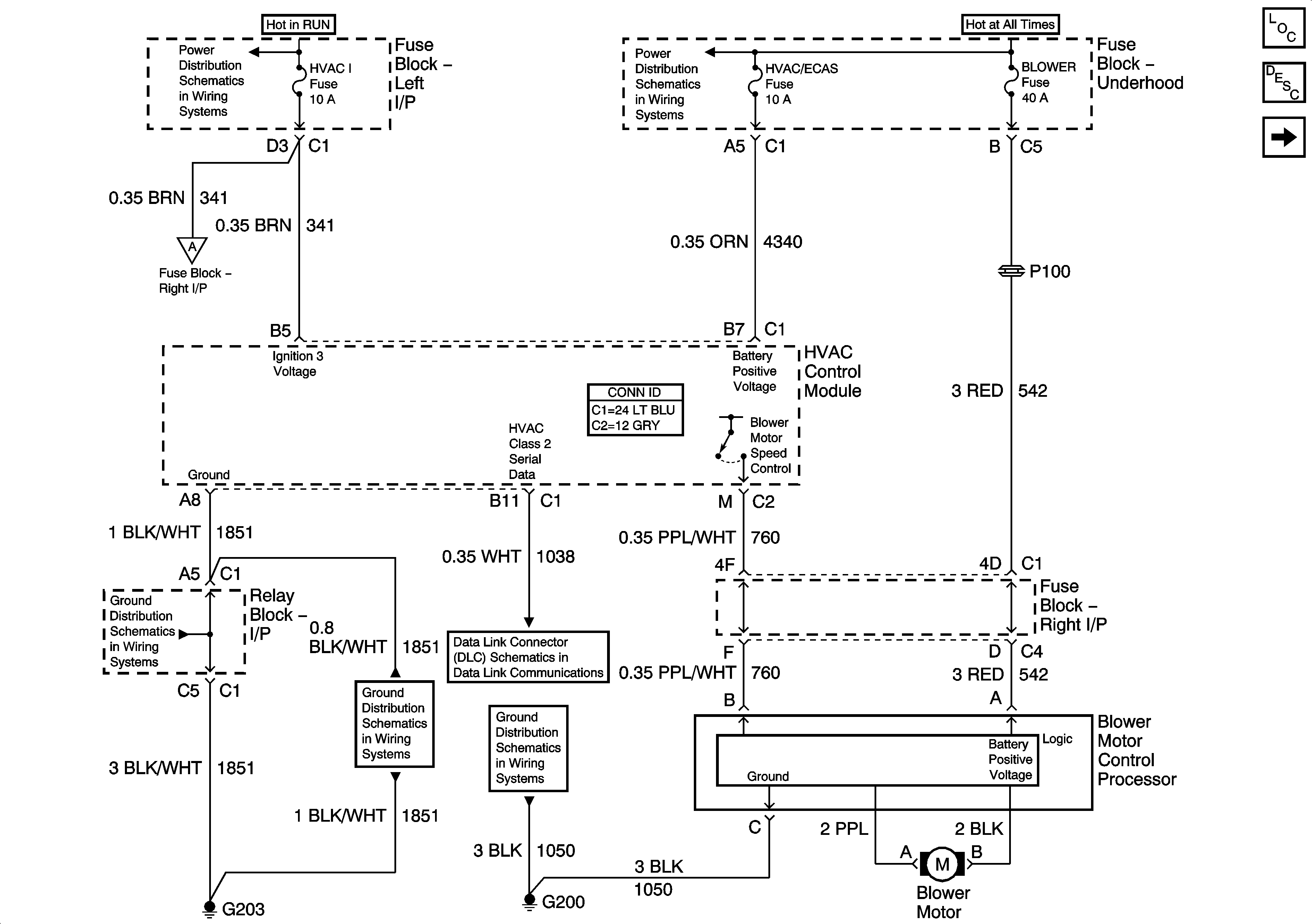

Object Number: 879563  Size: FS
Master Electrical Component List
Air Delivery Description and Operation
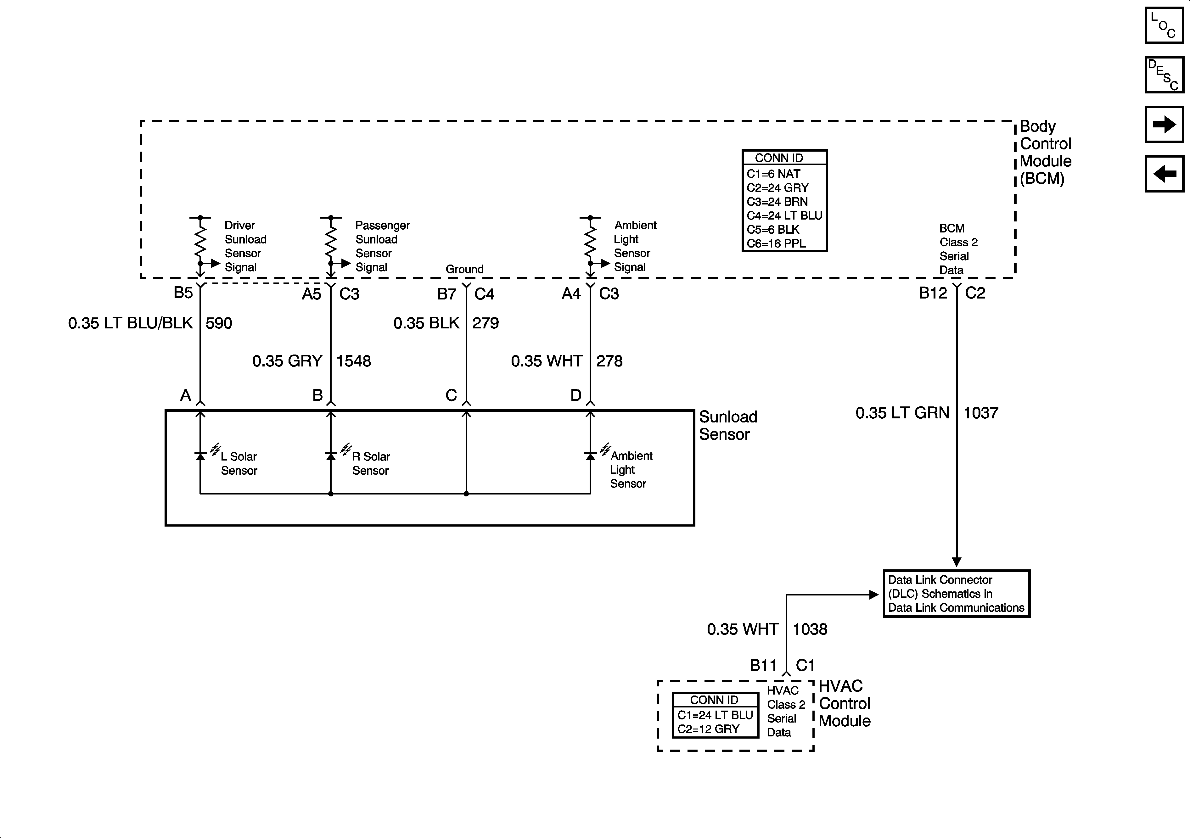
Sun Load and Ambient Light Sensors
HVAC/ECAS, RR HVAC, BLOWER, RR DEFOG, STOP LP, TREC
BRAKE, HTR/AC, HVAC I, CRUISE, 4WD
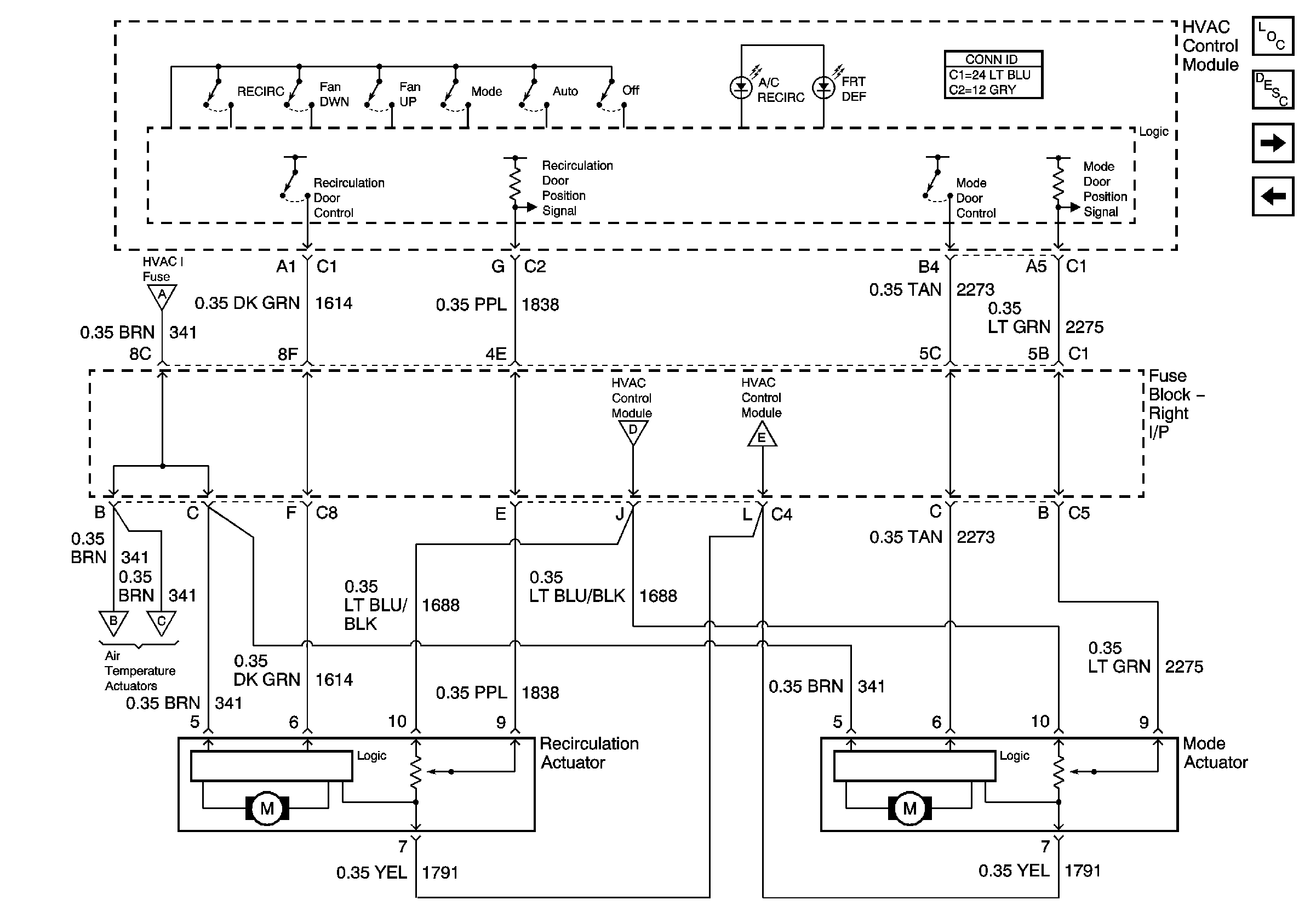
Recirculation and Mode Door Controls
G203 - 1 Of 2
G203 - 1 Of 2
SP205 - 1 of 2
G200 - 1 of 3
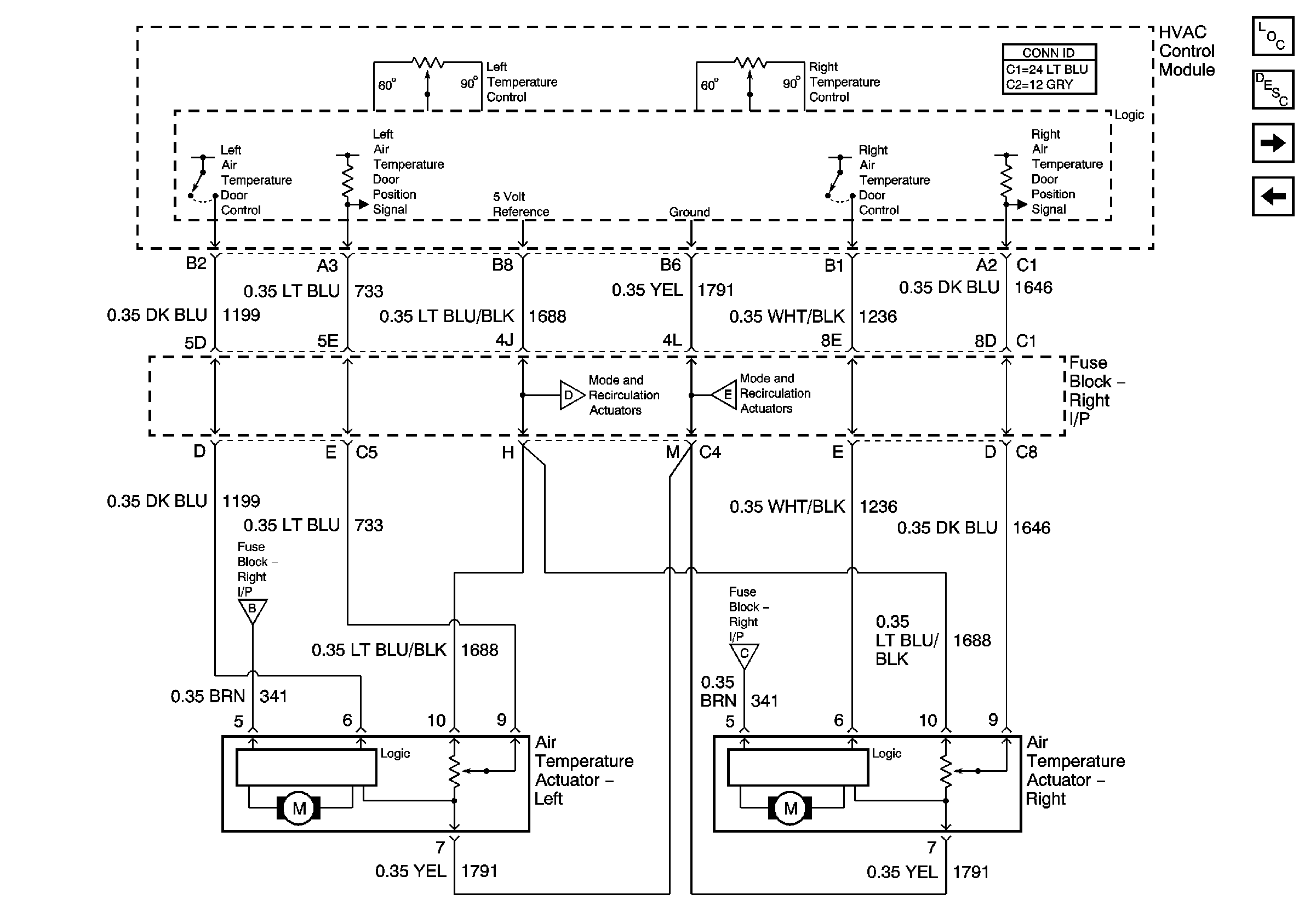
Figure 2:

Sun Load and Ambient Light Sensors


Object Number: 879564  Size: FS
Master Electrical Component List
Air Delivery Description and Operation
Front Left and Right Temperature Control
Power, Ground, Class2, and Front Blower Controls)
SP205 - 1 of 2
Figure 3:

Front Left and Right Temperature Control


Object Number: 879565  Size: FS
Master Electrical Component List
Air Delivery Description and Operation
Recirculation and Mode Door Controls
Sun Load and Ambient Light Sensors
Recirculation and Mode Door Controls
Figure 4:

Recirculation and Mode Door Controls


Object Number: 879566  Size: FS
Master Electrical Component List
Air Delivery Description and Operation
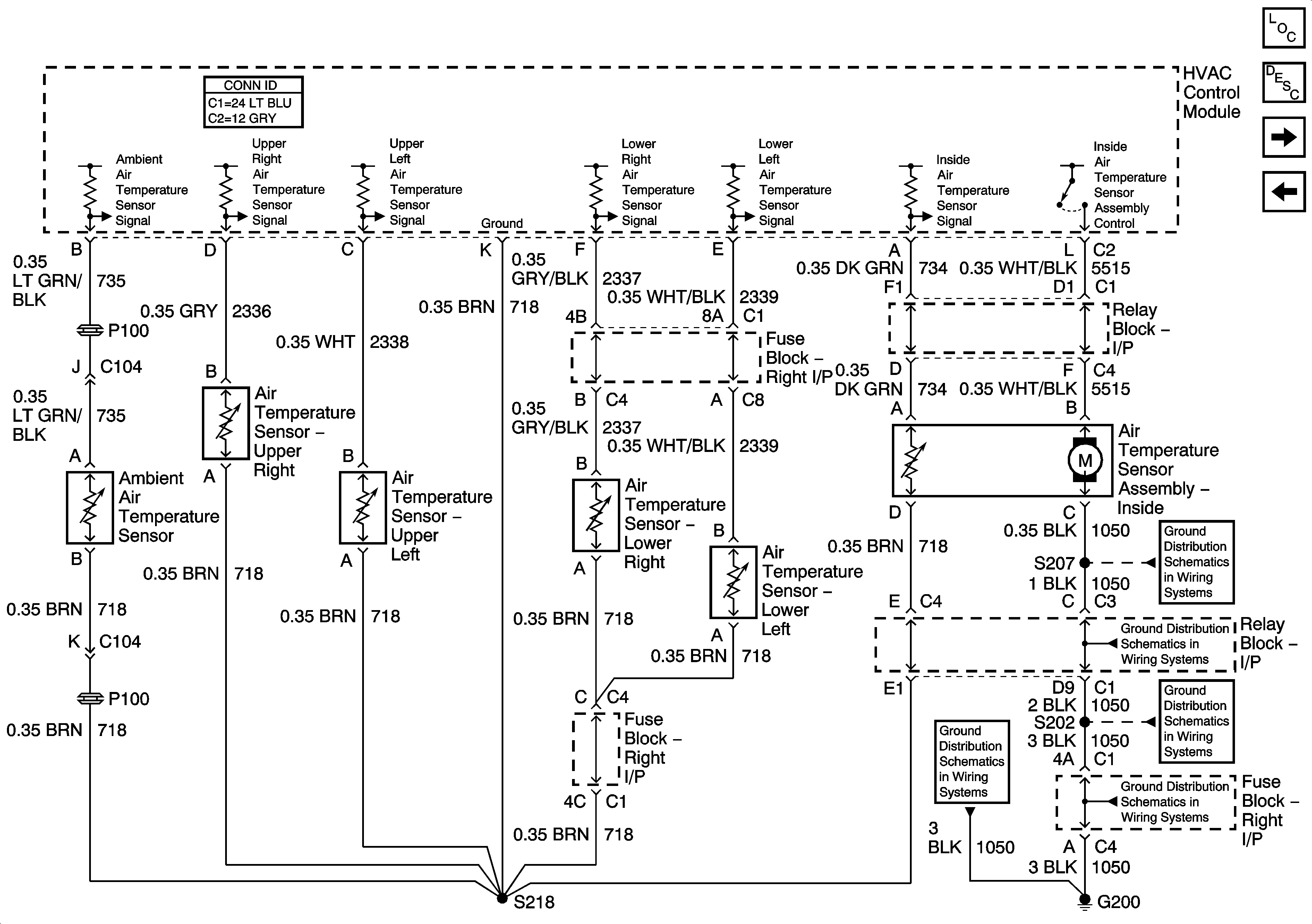
Front Air Temperature Sensors
Front Left and Right Temperature Control
Power, Ground, Class2, and Front Blower Controls)
Front Left and Right Temperature Control
Figure 5:

Front Air Temperature Sensors


Object Number: 879567  Size: FS
Master Electrical Component List
Air Temperature Description and Operation
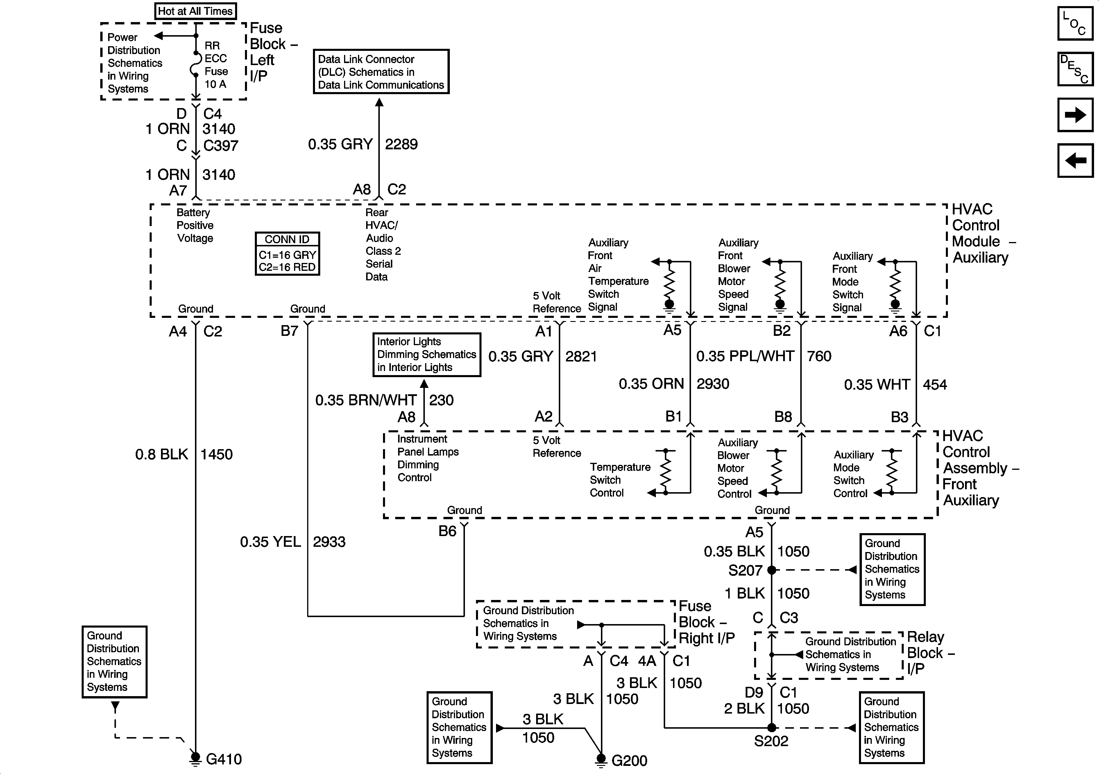
Auxiliary HVAC Controls - 1 of 3
Recirculation and Mode Door Controls
G200 - 3 Of 3
G200 - 3 Of 3
G200 - 1 of 3
G200 - 1 of 3
G200 - 1 of 3
Figure 6:

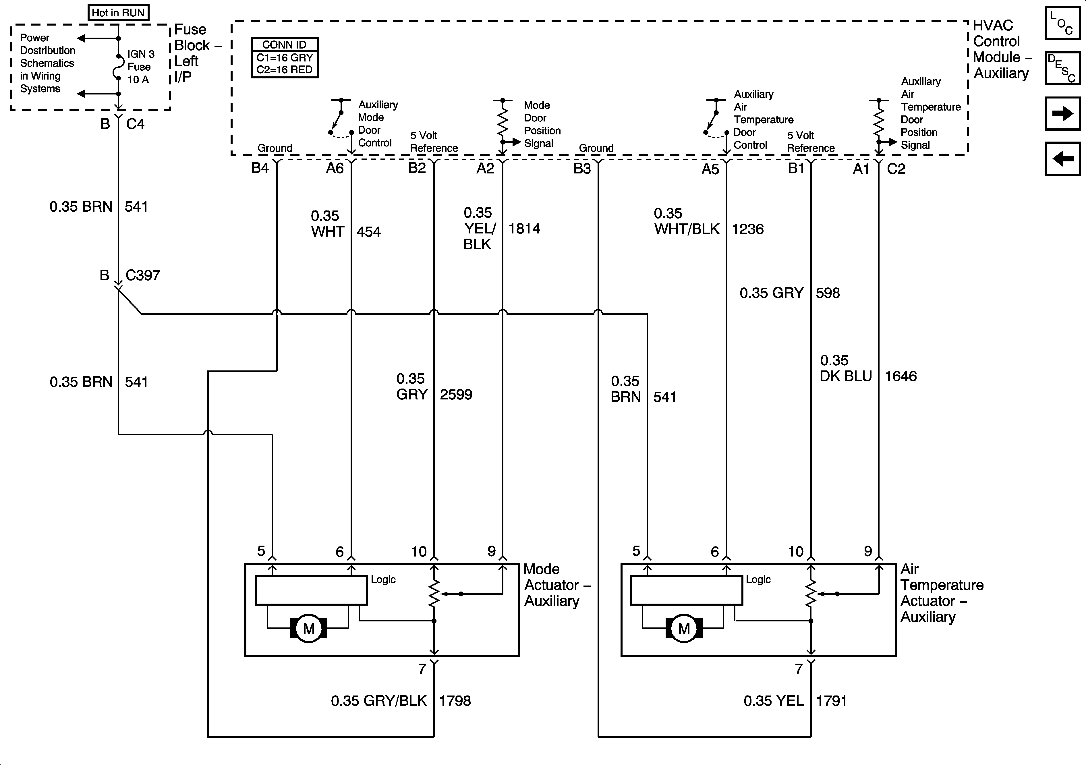
Auxiliary HVAC Controls - 1 of 3


Object Number: 879568  Size: FS
Master Electrical Component List
Air Delivery Description and Operation
Auxiliary HVAC Controls - 2 of 3
Front Air Temperature Sensors
DDM, PDM, ECC, AUX PWR 2, AUX PWR
SP206
I/P Dimming Supply Voltage - 6 of 7
G200 - 1 of 3
G200 - 1 of 3
G200 - 3 Of 3
G200 - 3 Of 3
G200 - 1 of 3
Figure 7:

Auxiliary HVAC Controls - 2 of 3


Object Number: 879569  Size: FS
Master Electrical Component List
Air Delivery Description and Operation
Auxiliary HVAC Controls - 3 of 3
Auxiliary HVAC Controls - 1 of 3
IGN 3
Figure 8:

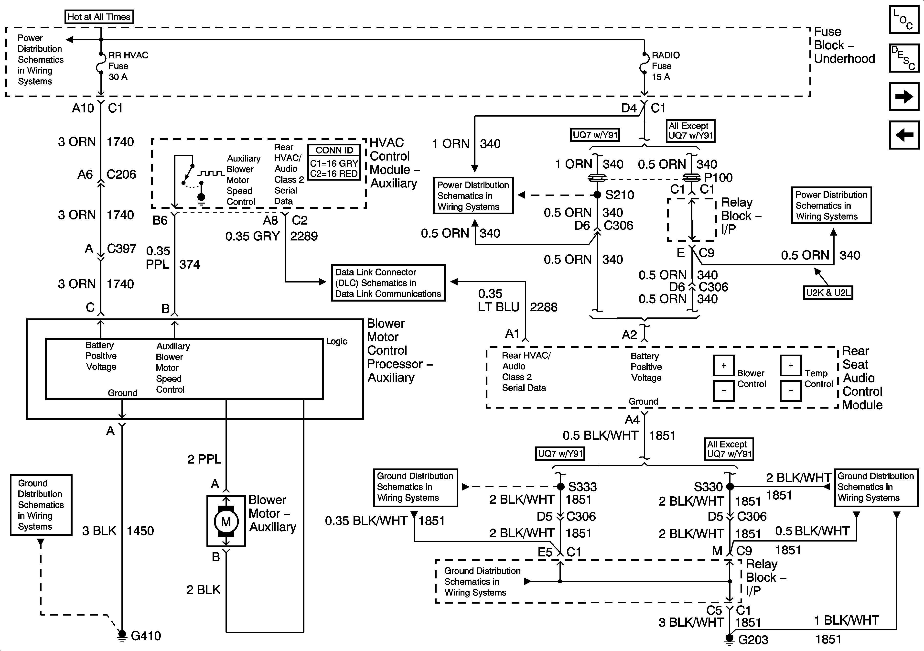
Auxiliary HVAC Controls - 3 of 3


Object Number: 879570  Size: FS
Master Electrical Component List
Air Delivery Description and Operation
Auxiliary Temperature Sensors
Auxiliary HVAC Controls - 2 of 3
HVAC/ECAS, RR HVAC, BLOWER, RR DEFOG, STOP LP, TREC
RADIO, RADIO AMP, 4WS
SP206
G203 - 1 Of 2
G203 - 1 Of 2
G410 - 1 Of 3
G203 - 1 Of 2
Figure 9:

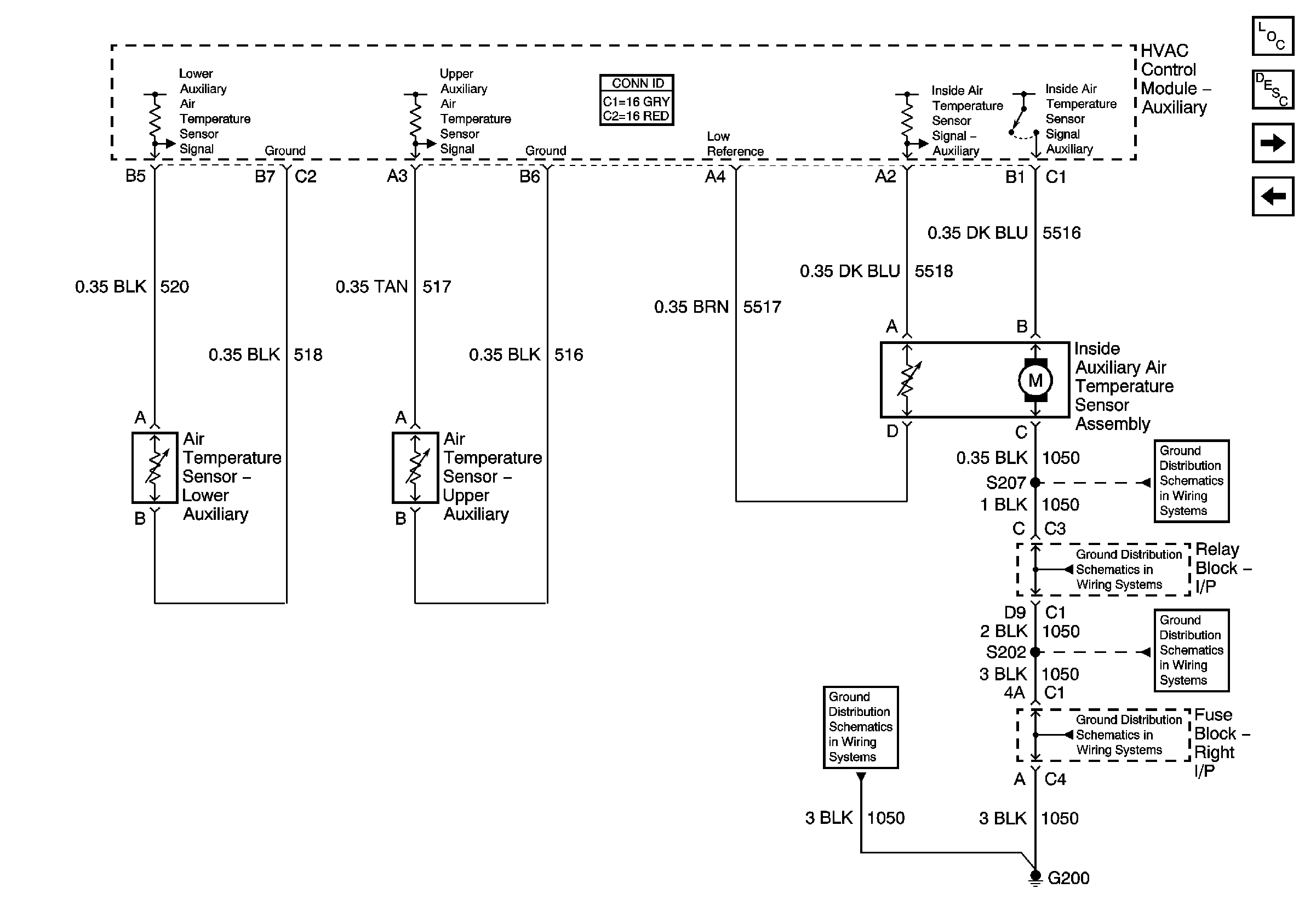
Auxiliary Temperature Sensors


Object Number: 879571  Size: FS
Master Electrical Component List
Air Delivery Description and Operation
A/C Compressor Controls
Auxiliary HVAC Controls - 3 of 3
G200 - 3 Of 3
G200 - 3 Of 3
G200 - 1 of 3
G200 - 1 of 3
G200 - 1 of 3
Figure 10:

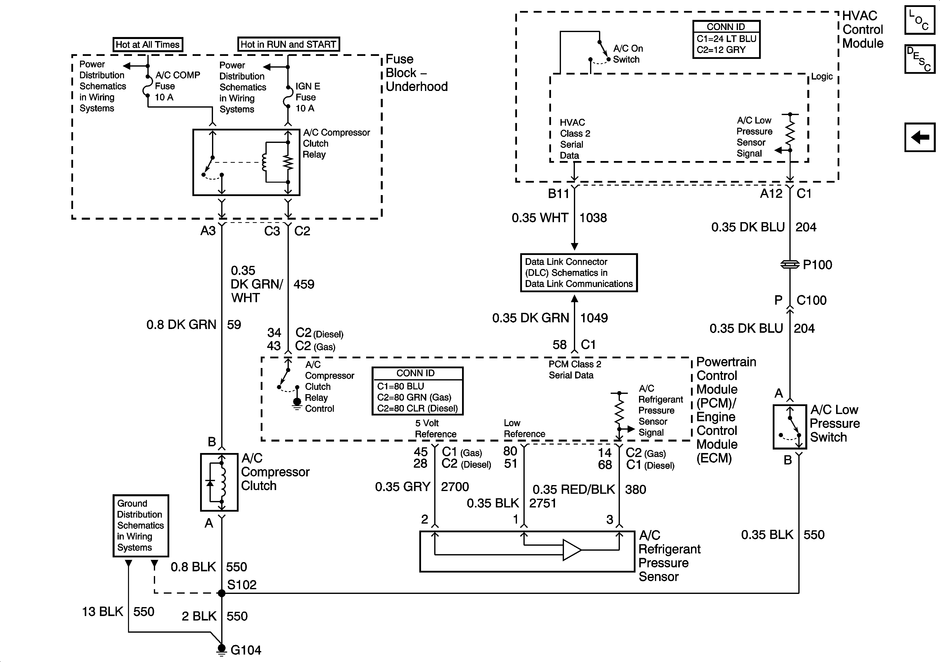
A/C Compressor Controls


Object Number: 879572  Size: FS
Master Electrical Component List
Air Temperature Description and Operation
Auxiliary Temperature Sensors
B+ Bus Bar - 2 of 2
IGN E
SP205 - 1 of 2
G104, G107