Air Temperature Door Replacement - Left Side Visteon
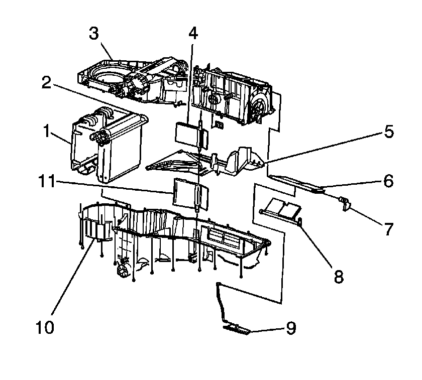
Removal Procedure
- Remove the HVAC module. Refer to HVAC Module Assembly Replacement .
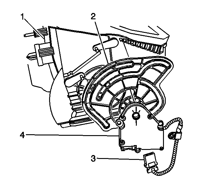
- Disconnect the electrical connector (3) from the mode actuator (4).
- Remove the screws from the mode actuator (4).
- Remove the mode actuator (4) from the HVAC module (1).
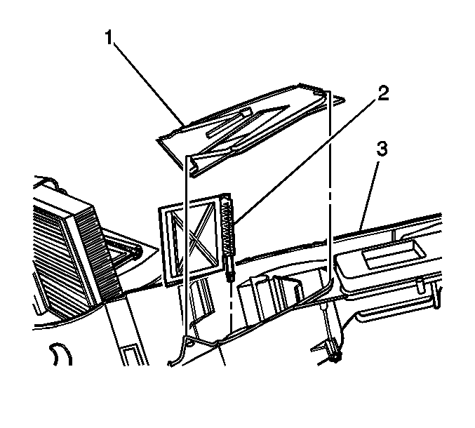
- Remove the wiring harness from the air distribution housing (1).
- Remove the screws from the air distribution housing (1).
- Remove the air distribution housing (1) from the HVAC module (2).
- Remove the screws from the upper recirulation housing (1).
- Remove the upper recirulation housing (1) from the HVAC module (2).
- Remove the screws from the lower recirulation housing (1).
- Remove the lower recirulation housing (1) from the HVAC module (2).
- Remove the wiring harness from the HVAC module.
- Remove the screws from the HVAC module.
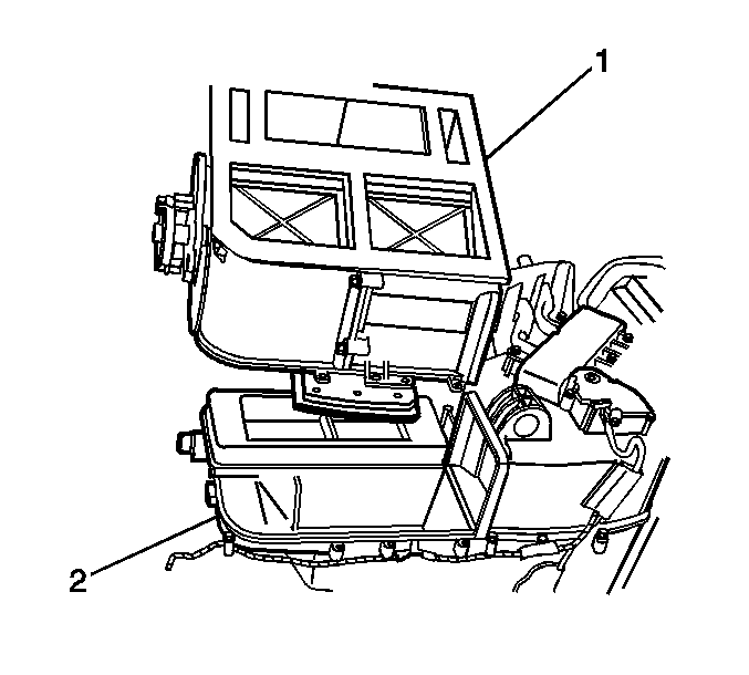
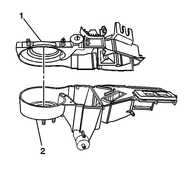
- Remove the upper HVAC module case (1) from the lower HVAC module case (2).
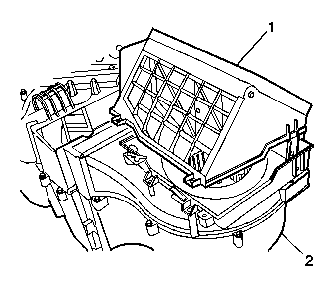
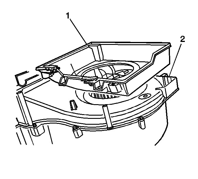
- Remove the HVAC module chamber plate (1) from the lower HVAC module case (3).
- Remove the left temperature door (2) from the lower HVAC module case (3).
Installation Procedure
- Install the left temperature door (2) to the lower HVAC module case (3).
- Install the HVAC module chamber plate (1) to the lower HVAC module case (3).
- Install the upper HVAC module case (1) to the lower HVAC module case (2).
- Install the screws to the HVAC module.
- Install the wiring harness to the HVAC module.
- Install the lower recirulation housing (1) to the HVAC module (2).
- Install the screws to the lower recirulation housing (1).
- Install the upper recirulation housing (1) to the HVAC module (2).
- Install the screws to the upper recirulation housing (1).
- Install the air distribution housing (1) to the HVAC module (2).
- Install the screws to the air distribution housing (1).
- Install the wiring harness to the air distribution housing (1).
- Install the mode actuator (4) to the HVAC module (1).
- Install the screws to the mode actuator (4).
- Connect the electrical connector (3) to the mode actuator (4).
- Install the HVAC module. Refer to HVAC Module Assembly Replacement .
Notice: Use the correct fastener in the correct location. Replacement fasteners must be the correct part number for that application. Fasteners requiring replacement or fasteners requiring the use of thread locking compound or sealant are identified in the service procedure. Do not use paints, lubricants, or corrosion inhibitors on fasteners or fastener joint surfaces unless specified. These coatings affect fastener torque and joint clamping force and may damage the fastener. Use the correct tightening sequence and specifications when installing fasteners in order to avoid damage to parts and systems.
Tighten
Tighten the screws to 2 N·m (18 lb in).
Tighten
Tighten the screws to 2 N·m (18 lb in).
Tighten
Tighten the screws to 2 N·m (18 lb in).
Tighten
Tighten the screws to 2 N·m (18 lb in).
Tighten
Tighten the screws to 2 N·m (18 lb in).
Air Temperature Door Replacement - Left Side Delphi
Removal Procedure
- Remove the HVAC module. Refer to HVAC Module Assembly Replacement .
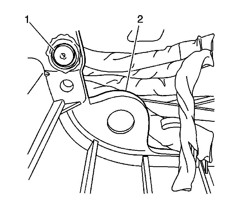
- If equipped remove the heat stakes (1) from the HVAC module (2) with a screw driver and a hammer.
- If equipped remove the HVAC module assembly screws.
- Remove the upper HVAC module case (3) from the lower HVAC module case (10).
- Remove the air temperature separator plate (5) from the lower HVAC module case (10).
- Remove the left temperature door (11) from the lower HVAC module case (10).
Installation Procedure
- Install the left temperature door (11) to the lower HVAC module case (10).
- Install the air temperature separator plate (5) to the lower HVAC module case (10).
- Install the upper HVAC module case (3) to the lower HVAC module case (10).
- Install the screws to the HVAC module assembly.
- Install the HVAC module. Refer to HVAC Module Assembly Replacement .
Notice: Refer to Fastener Notice in the Preface section.
Important: For every heat stake removed ensure that you install a screw.
Tighten
Tighten the screws to 1.6 N·m (14 lb in).
