Tools Required
| • | J 35910
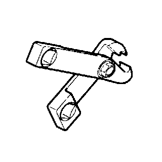
Drive Axle Seal Clamp Pliers |
Removal Procedure
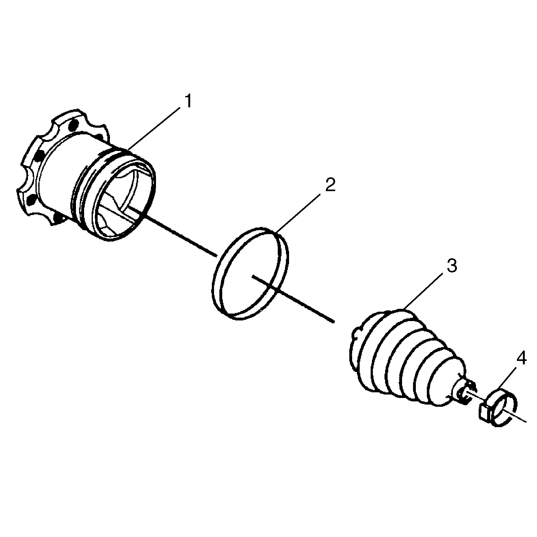
- Remove the wheel drive shaft. Refer to
Wheel Drive Shaft Replacement
.
- Remove the wheel drive shaft seal cover, if applicable. Refer to
Wheel Drive Shaft Seal Cover Replacement
.
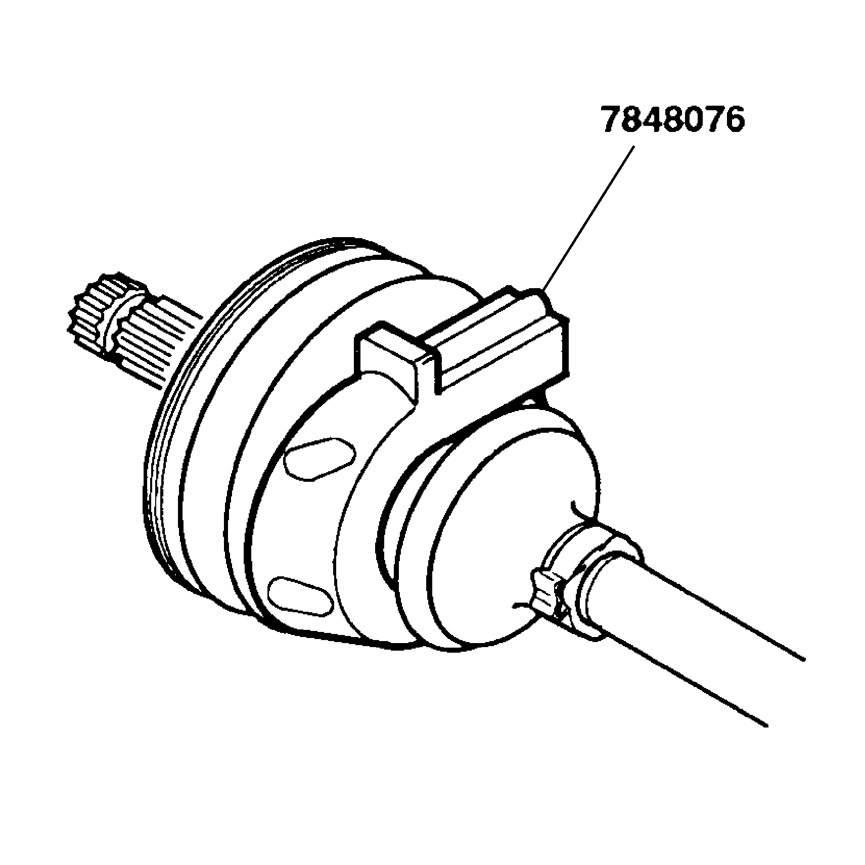
Important: Use caution when using the hand grinder by the tripot housing (1).
- Use a hand grinder in order to cut through the swage ring (2).
- Remove the tripot housing (1) from the halfshaft.
- Wipe the grease off of the housing (1).
- Thoroughly degrease the tripot housing (1).
- Allow the tripot housing (1) to dry prior to assembly.
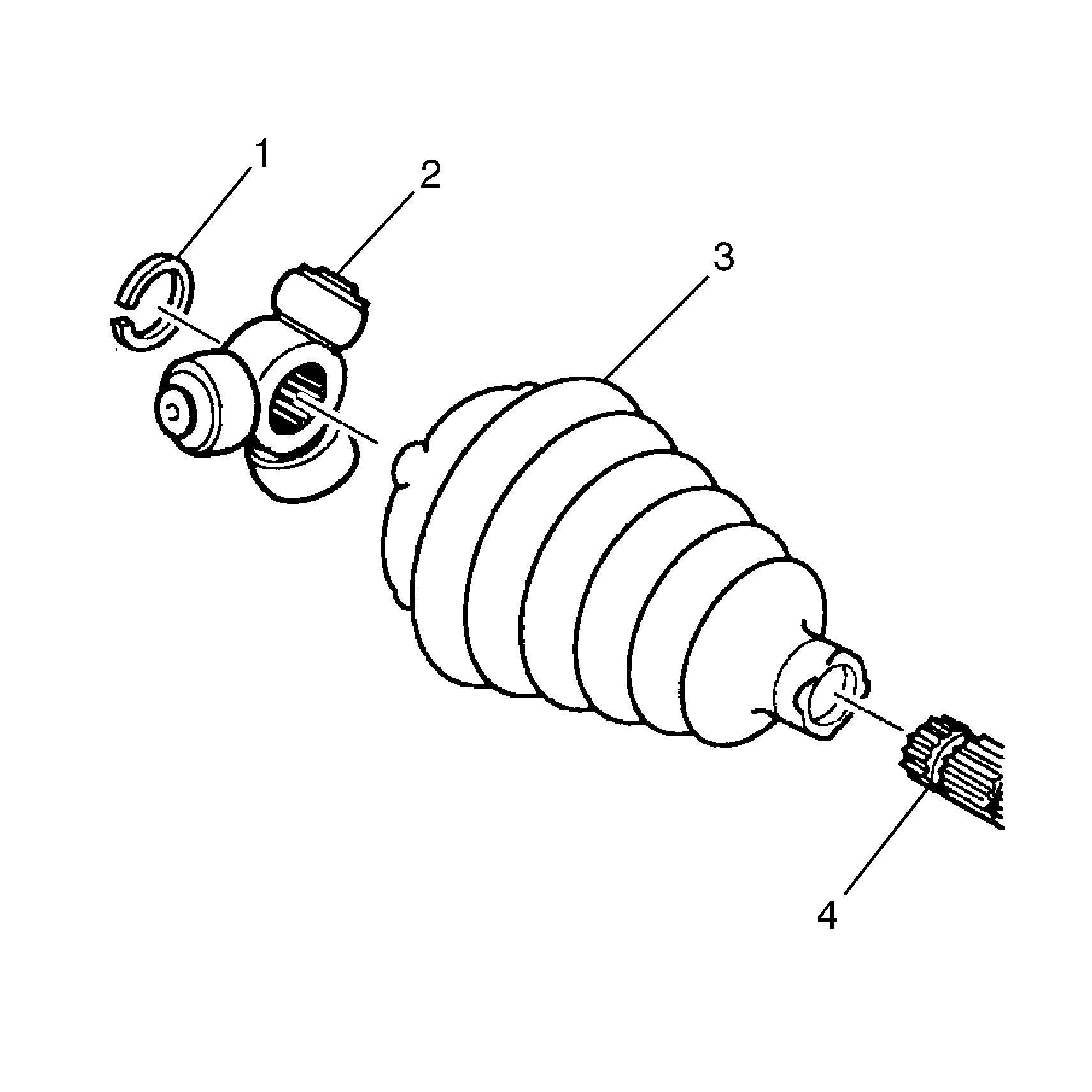
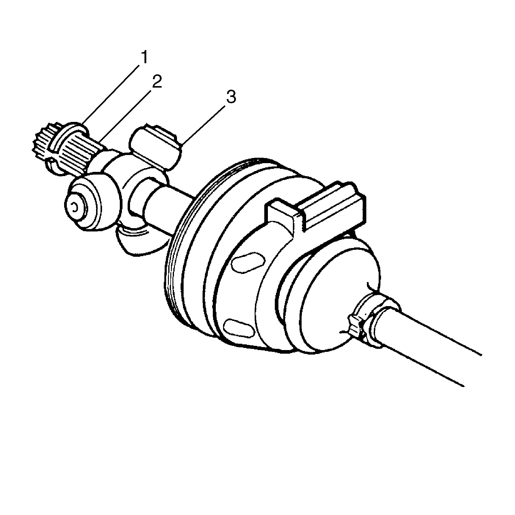
- Using side cutters, remove the small boot retaining clamp.
- Remove the following items from the halfshaft bar:
| 9.2. | The tripot spider assembly (2) |
- Clean the halfshaft bar (4). Use a wire brush in order to remove any rust in the seal mounting area (grooves).
- Inspect the needle rollers, needle bearings, and trunnion. Inspect the tripot housing for unusual wear, cracks, or other damage. Replace any damaged parts with the appropriate service kit.
Installation Procedure
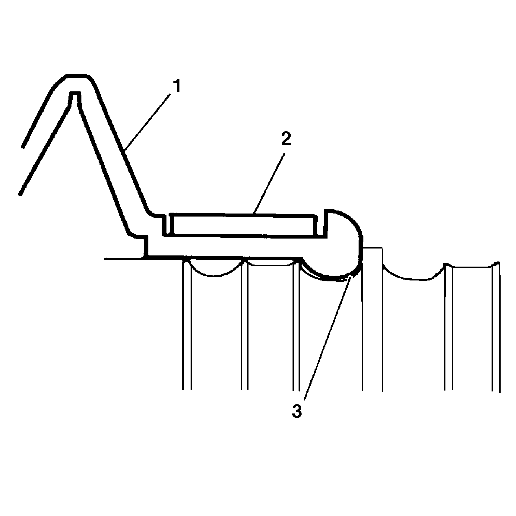
- Place the new small seal clamp (2) onto the small end of the joint seal (1). Compress the joint seal (1) and
small seal clamp (2) onto the halfshaft bar.
- Position the small end of the joint seal (1) into the joint seal groove (3) on the halfshaft bar.
Notice: Refer to Fastener Notice in the Preface section.
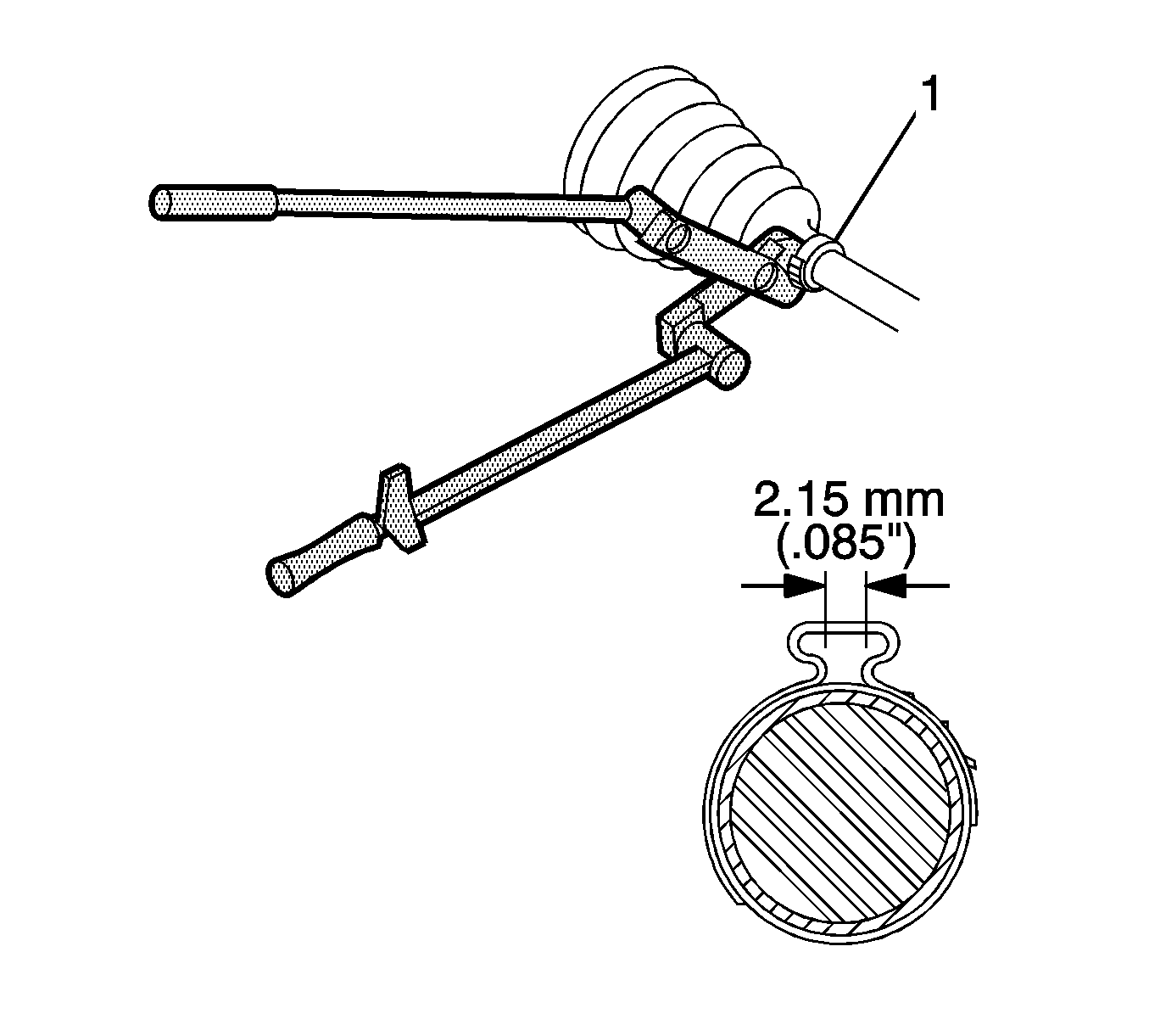
- Secure the small seal clamp (1) with
J 35910
, or equivalent, a breaker bar, and a torque wrench.
Tighten
Tighten the small seal clamp (1) to 136 N·m (100 lb ft).
- Inspect the gap dimension on the clamp ear. Continue tightening until the gap dimension is reached.
Important: Assemble the tripot joint with the convolute retainer in the correct position, as illustrated.
- Install the convolute retainer tool over the inboard joint seal, being sure to capture the following convolutions:
| • | 2-5 for the 1500 model. |
| • | 2-4 for the 2500 and 3500 models. |
- Install the tripot spider assembly (3) onto the halfshaft bar (2).
- Install the spacer ring (1) in the groove at the end of the halfshaft bar (2).
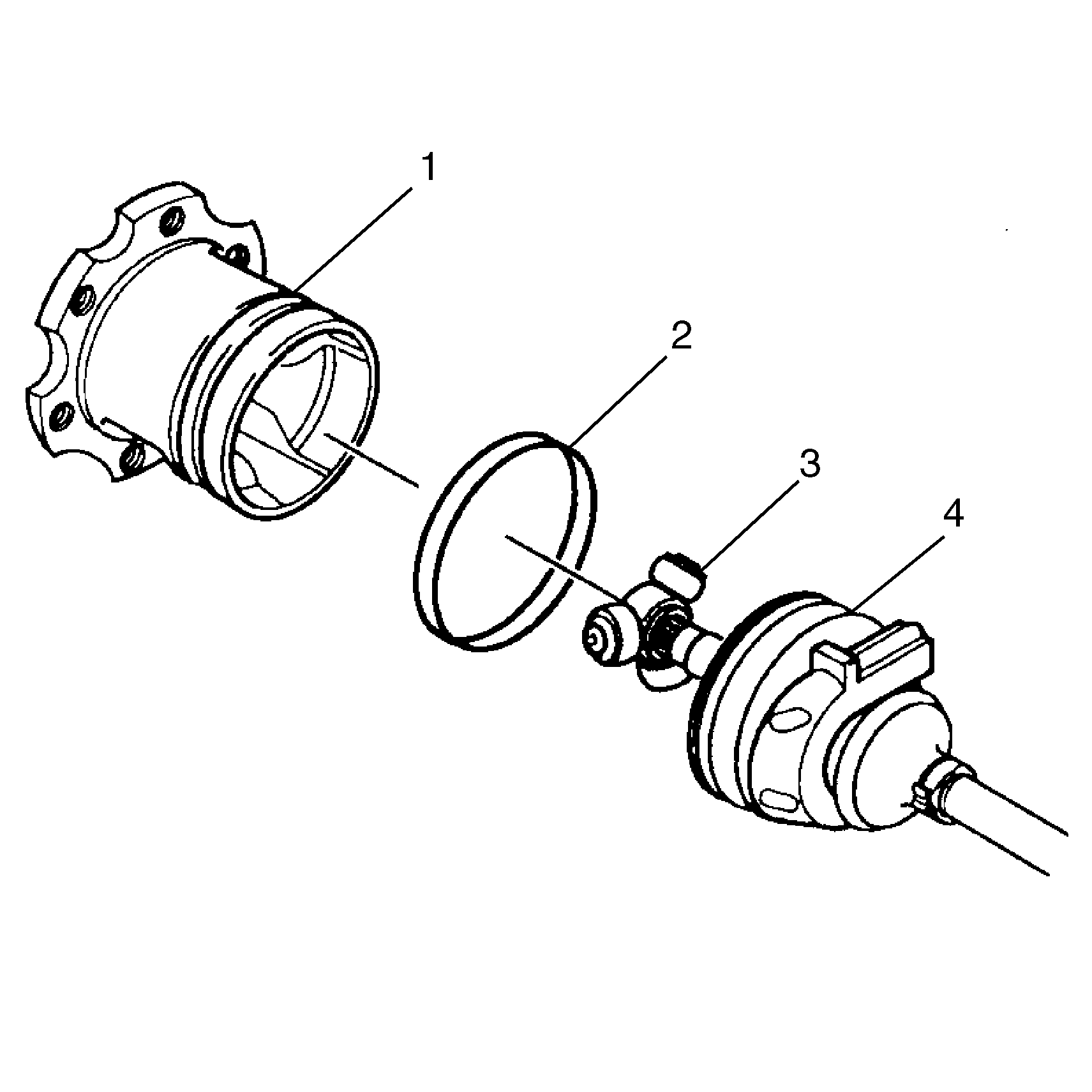
- Pack the tripot seal (4) and the tripot housing (1) with the grease supplied in the kit.
The amount of grease supplied in this kit has been pre-measured for this application.
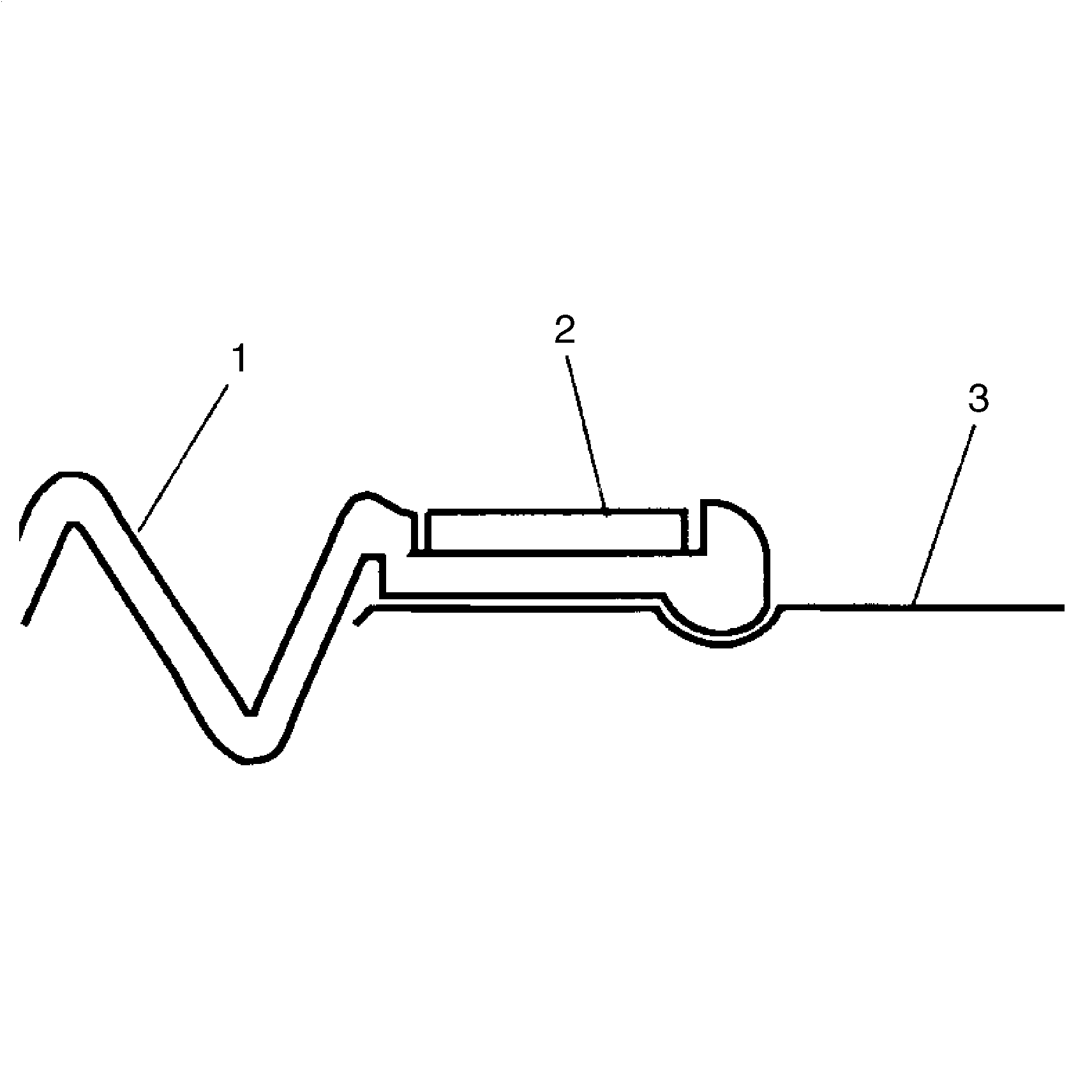
- Assemble the tripot housing and the tripot seal using the following procedure:
| 9.1. | Pinch the swage ring (2) slightly by hand in order to distort it into an oval shape. |
| 9.2. | Slide the distorted swage ring (2) over the large diameter of the seal. |
| 9.3. | Place the tripot housing over the spider assembly. |
| 9.4. | Install the seal onto the tripot housing. |
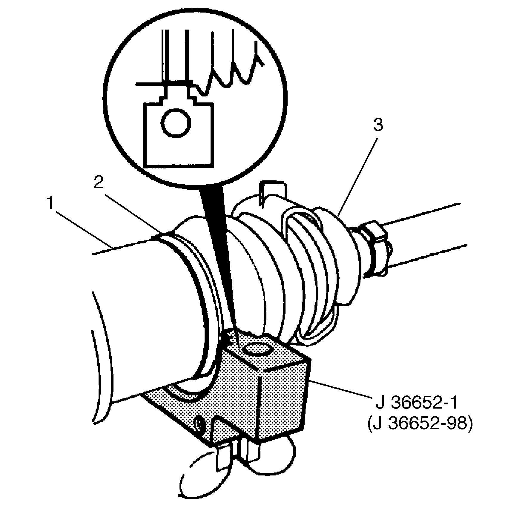
| 9.5. | Align the tripot seal (1), with the swage ring (2) in place, over the flat area on the tripot housing (3). |
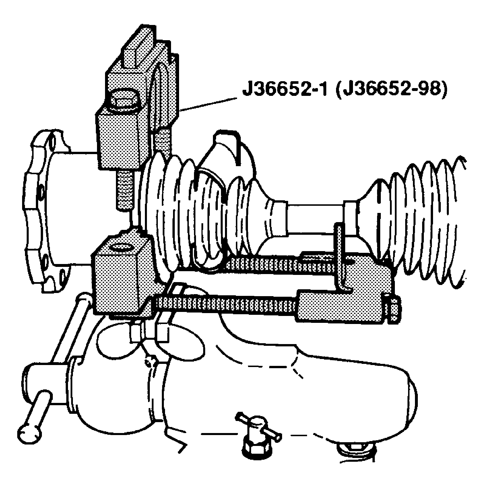
- For the 1500 models, assemble the bolts and the support plate to the base
of the
J 36652-98
and secure the base in a vise.
- For the 2500 and 3500 models, assemble the bolts and the support plate to the base of the
J 36652-1
and secure the base in a vise.
- Position the inboard end (tripot end) of the halfshaft assembly into the base of the
J 36652-98
for the 1500 models or
J 36652-1
for the 2500 and 3500 models.
- Install the top half of the
J 36652-98
for the 1500 models or
J 36652-1
for the 2500 and 3500 models.
- Align the swage ring (2) and the swage ring clamp.
- Insert the bolts.
Tighten
Hand tighten the bolts until the bolts are snug.
- Align the following during this procedure:
Tighten
Tighten each bolt 180 degrees at a time. Alternate between the bolts until both sides of the top half of the tool touch the bottom half .
| • | Loosen the bolts and remove the halfshaft assembly from the tool. |
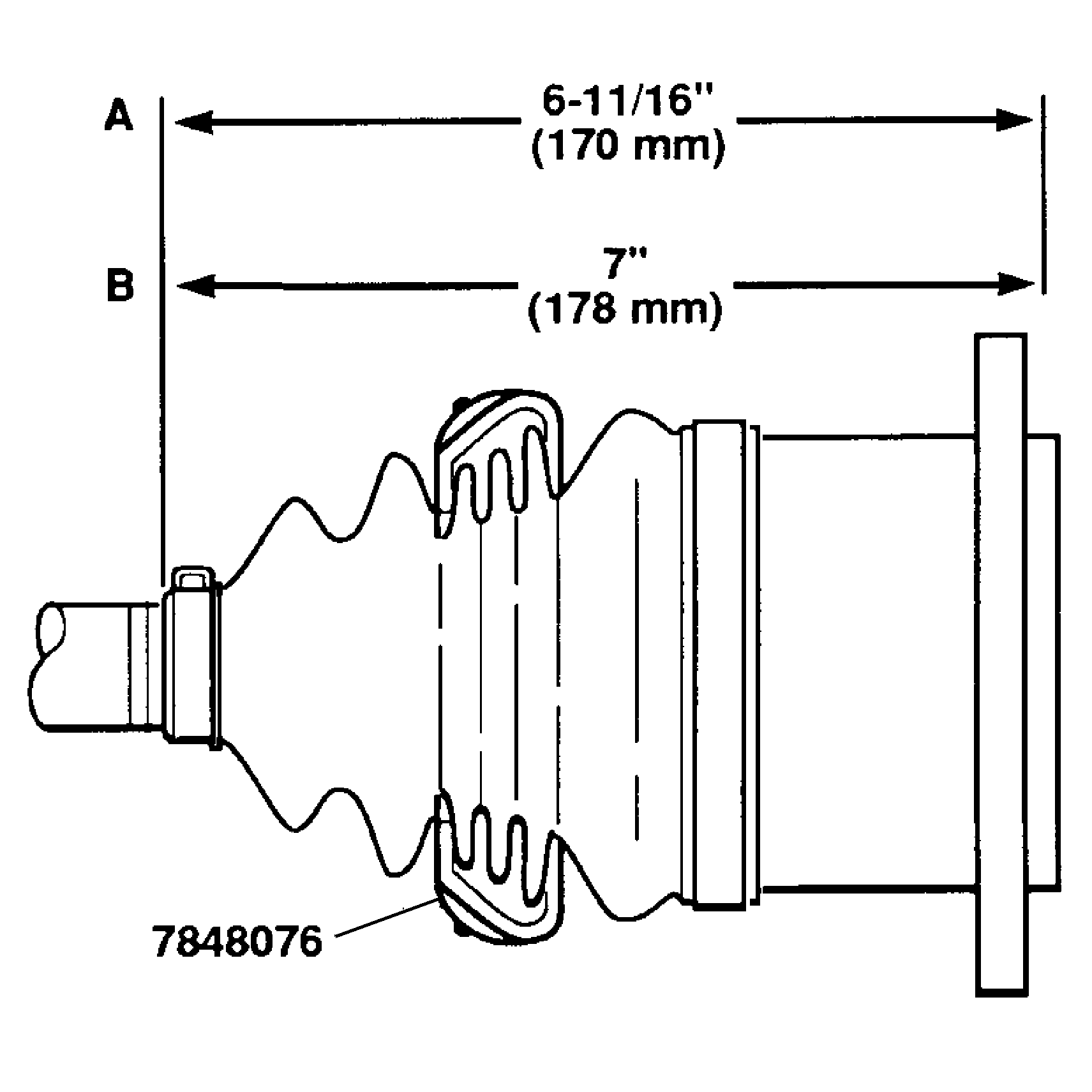
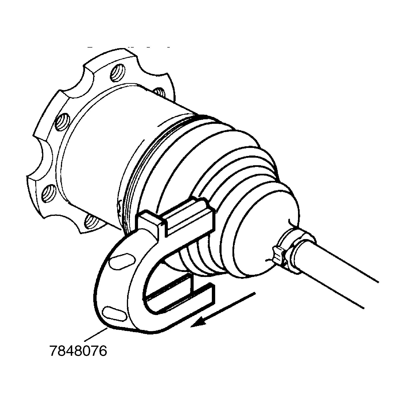
- Inspect the inboard stroke position.
| • | Use measurement A for the 1500 models. |
| • | Use measurement B for the 2500 and 3500 models. |
- Remove the convolute retainer tool from the boot.
- Install the wheel drive shaft seal cover, if applicable. Refer to
Wheel Drive Shaft Seal Cover Replacement
.
- Install the wheel drive shaft. Refer to
Wheel Drive Shaft Replacement
.
