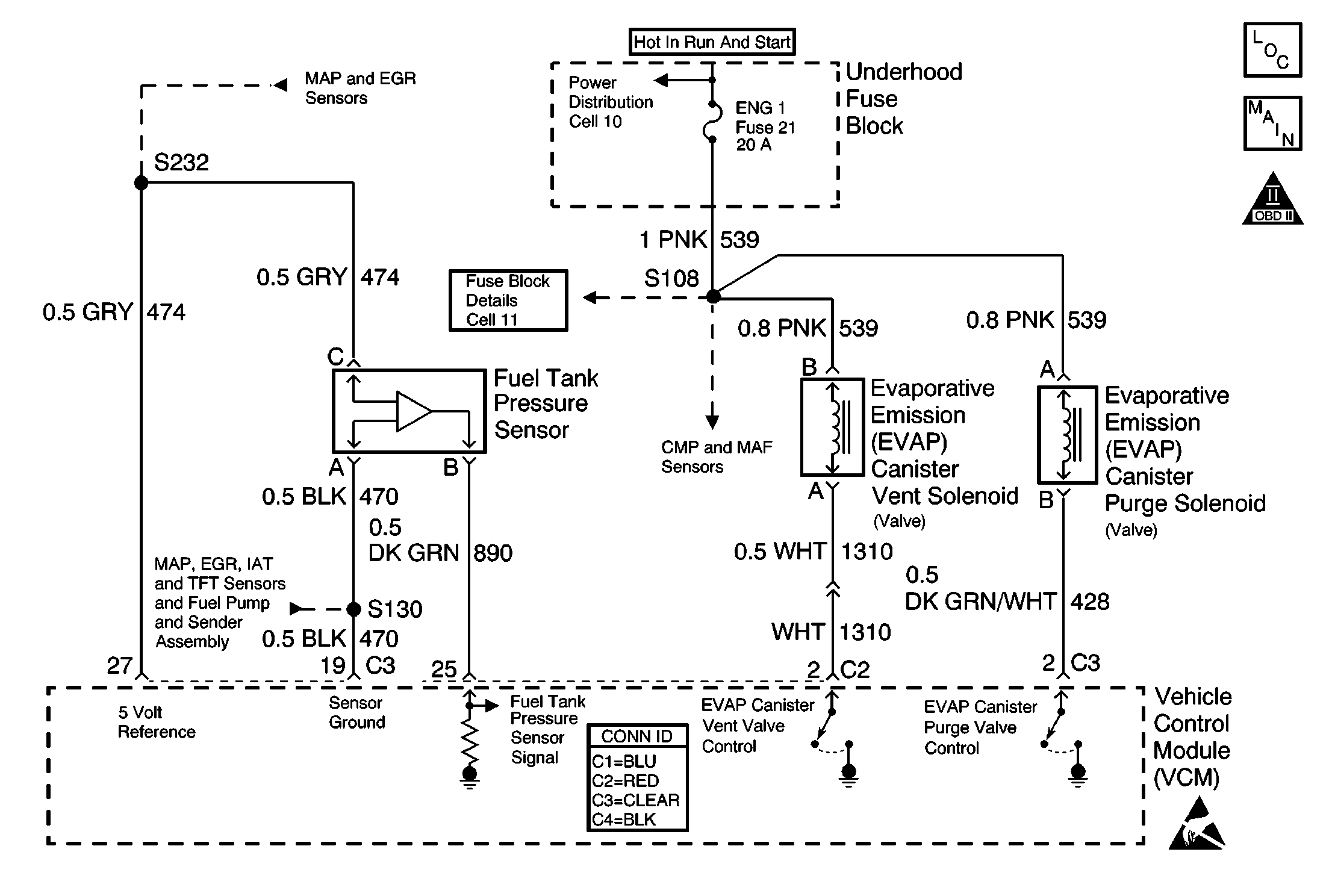
Circuit Description
The vehicle control module (VCM) monitors the performance of the evaporative emission (EVAP) system by applying a predetermined level of vacuum to the EVAP system and then it monitors the vacuum decay rate. The VCM sets this diagnostic trouble code (DTC) if the vacuum decay rate is more than a predetermined value. The VCM monitors the amount of vacuum and the amount of pressure in the EVAP system by monitoring the fuel tank pressure sensor. For this DTC, the VCM turns ON both the EVAP purge valve and the EVAP vent valve when the Conditions for Running the DTC are met. This applies an engine vacuum to a closed EVAP system. The VCM turns OFF both the EVAP purge valve and the EVAP vent valve when the system reaches a correct amount of vacuum. The EVAP system should quickly RELEASE the vacuum in the EVAP system with the EVAP purge valve OFF and the EVAP vent valve OFF, or open. This test indicates a blocked or restricted EVAP vent valve or path if the EVAP system fails to release the vacuum quickly enough.
Conditions for Running the DTC
| • | No active manifold absolute pressure (MAP) sensor DTCs |
| • | No active throttle position (TP) sensor DTCs |
| • | No active vehicle speed sensor (VSS) DTCs |
| • | No active oxygen (O2) sensor DTCs |
| • | No active engine coolant temperature (ECT) sensor DTCs |
| • | No active intake air temperature (IAT) sensor DTCs |
| • | DTC P0125 not active |
| • | The fuel level is between 12.5-87 percent. |
| • | The system voltage is between 10-17 volts. |
| • | The ECT is between 4-30°C (39-86°F). |
| • | The IAT is between 4-30°C (39-86°F). |
| • | The cold start temperature difference, which is ECT minus IAT, is less than |
| - | 1.5°C (35°F) when the IAT is more than the ECT |
| - | OR |
| - | 8°C (46°F) when the ECT is more than the IAT. |
| • | The BARO is more than 72 kPa. |
| • | The change in fuel tank vacuum is less than 0.6 in. of H2O, or the change in fuel level is less than 8 percent. |
| • | The fuel tank vacuum level remains above a calibrated value for a specified number of seconds. |
Conditions for Setting the DTC
The VCM fails to detect a drop in the EVAP system vacuum over a calibrated number of seconds with the vent solenoid open.
Action Taken When the DTC Sets
| • | The VCM illuminates the malfunction indicator lamp (MIL) during the first key cycle in which the DTC sets. |
| • | The VCM stores the conditions that were present when the DTC sets as Freeze Frame and Fail Records data. |
Conditions for Clearing the MIL or DTC
| • | The control module turns OFF the MIL after 3 consecutive drive trips when the test has run and passed. |
| • | A history DTC will clear if no fault conditions have been detected for 40 warm-up cycles. A warm-up cycle occurs when the coolant temperature has risen 22°C (40°F) from the startup coolant temperature and the engine coolant reaches a temperature that is more than 70°C (158°F) during the same ignition cycle. |
| • | Use a scan tool in order to clear the DTCs. |
Diagnostic Aids
Important: An accurate indication of fuel level is required for the VCM to properly Pass or Fail this DTC. Always diagnose the fuel level sensor DTCs before performing this DTC diagnostic table. Always check for fuel level sensor DTCs stored in History.
Check for the following conditions:
| • | A loose, missing, damaged, incorrect, or improperly installed fuel cap |
| • | Missing or damaged O-rings at EVAP canister fuel vapor and purge line fittings |
| • | A cracked or punctured EVAP canister |
| • | Incorrectly routed or defective EVAP system vacuum and vapor lines |
| • | A damaged or disconnected EVAP purge line, vent hose, or fuel tank vapor line |
| • | A stuck closed EVAP vent valve |
| • | A restricted or stuck closed fuel tank rollover valve |
| • | A poor connection at the VCM -- Inspect the harness connectors for the following conditions: |
| - | Backed out terminals |
| - | Improper mating |
| - | Broken locks |
| - | Improperly formed or damaged terminals |
| - | Poor terminal to wire connection |
| • | A damaged harness -- Inspect the wiring harness to the EVAP vent solenoid, the EVAP purge solenoid, and the fuel tank pressure sensor for an intermittent, open, or short circuit. |
| • | A kinked, pinched, or plugged EVAP purge or fuel tank vapor line -- Verify that the lines are not restricted. |
Refer to Evaporative Emission System Cleaning before starting the repairs.
Reviewing the Fail Records vehicle mileage since the diagnostic test last failed may help determine how often the condition that caused the DTC to be set occurs. This may assist in diagnosing the condition.
Test Description
The numbers below refer to the step numbers on the diagnostic table.
-
If the vacuum stored in the EVAP system is quickly released, then an intermittent system restriction or failure of the EVAP vent valve or the EVAP fuel tank pressure sensor may have occurred.
-
Check the vapor canister and the EVAP vent valve for restriction.
-
An EVAP pressure sensor that does not correctly respond to pressure or vacuum will cause this DTC to set. The EVAP pressure sensor monitors a range from +7.5 in. H2O of pressure to -17.5 in. H2O of pressure or vacuum. In order to test the EVAP pressure sensor for pressure response, SEAL the system with the scan tool and use the EVAP pressure/purge diagnostic cart to apply pressure to the system. Compare the pressure gauge (in. H2O) on the diagnostic cart to the EVAP pressure sensor reading on the scan tool.
Step | Action | Value(s) | Yes | No | ||||
|---|---|---|---|---|---|---|---|---|
1 | Did you perform the Powertrain On-Board Diagnostic (OBD) System Check? | -- | ||||||
2 |
Was a repair made to the EVAP system? | -- | ||||||
3 | Are DTCs P0452 or P0453 also set? | -- | Go to the applicable DTC table | |||||
Does the EVAP fuel tank pressure sensor quickly drop to near 0 in. H2O when 0 percent EVAP purge is commanded and the EVAP vent valve is opened? | -8 in. H2O | Go to Diagnostic Aids | ||||||
Does the vacuum drop from the specified value when the EVAP vent valve is opened? | 5 in. Hg | |||||||
6 |
Does the vacuum drop from the specified value when the vent line is unplugged? | 5 in. Hg | ||||||
7 |
Was the EVAP vent line replaced? | -- | ||||||
8 |
Was the fuel tank vapor line replaced? | -- | ||||||
|
Important: The following steps require the J 41413 EVAP pressure/purge diagnostic station. Always zero the EVAP pressure and vacuum (in. H2O) gauges on the J 41413 EVAP pressure/purge diagnostic station before proceeding with diagnosis.
Do both values indicate the same amount of vacuum in the EVAP system to within the range specified? | +/-2 in. H2O | |||||||
10 |
Is the test lamp illuminated? | -- | ||||||
11 |
Was a problem found? | -- | ||||||
12 | Replace the EVAP vent valve. Refer to Evaporative Emission Vent Valve Replacement . Is the replacement complete? | -- | -- | |||||
13 | Replace the EVAP vapor canister. Refer to Evaporative Emission Canister Replacement . Is the replacement complete? | -- | -- | |||||
14 | Replace the EVAP fuel tank pressure sensor. Refer to Fuel Tank Pressure Sensor Replacement . Is the replacement complete? | -- | -- | |||||
15 |
Important: The replacement VCM must be programmed. Replace the VCM. Refer to VCM Replacement/Programming . Is the action complete? | -- | -- | |||||
16 |
Does the scan tool indicate the diagnostic Passed? | -- | -- | |||||
17 | Does the scan tool display any additional undiagnosed DTCs? | -- | Go to the applicable DTC table | System OK |
