Removal Procedure
- Raise the vehicle on a hoist.
Important: Observe and accurately reference mark all driveline components relative
to the propeller shaft and axles before disassembly. These components include
the propeller shafts, drive axles, pinion flanges, output shafts, etc.
All components must be reassembled in the exact relationship to each other
as they were when removed. In addition, published specifications and torque
values, as well as any measurements made prior to disassembly must be followed.
- Reference mark the propeller shaft to pinion flange connection.
- Reference mark the slip yoke to the transmission for proper reassembly.
- When servicing propeller shafts with the pop on seal, do not remove
the seal from the sleeve. Removal of the seal causes damage to the seal lip
where it contacts the sleeve yoke. If removal of the seal is necessary, replace
the seal with a new part.
- Remove the retainer bolts.
- Remove the retainers.
Notice: When removing the propeller shaft, do not attempt to remove the shaft
by pounding on the yoke ears or using a tool between the yoke and the universal
joint. If the propeller shaft is removed by using such means, the injection
joints may fracture and lead to premature failure of the joint.
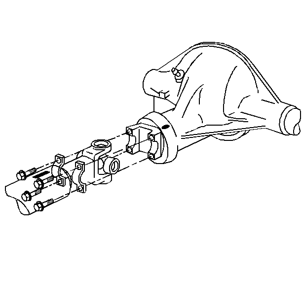
- Remove the yoke and cross assembly, wrapping the bearing cups with tape
in order to prevent the loss of bearing rollers.
- For two-piece Dana propeller
shafts, pull the slip yoke (4) out of the stub shaft (1).
- For two-piece American Axle and Manufacturing propeller shafts,
unscrew the threaded cap on the center slip yoke.
- Remove the propeller shaft.
| 10.1. | Slide the propeller shaft forward. |
| 10.2. | Lower the propeller shaft and remove the propeller shaft. |
| 10.3. | Do not allow the universal joint to incline greatly. The joint
may fracture. |
- Remove the center bearing support bolts.
- Remove the center support bearing nuts and washers.
- Remove the center bearing support (3).
- Remove the front propeller shaft.
| 14.1. | Support the propeller shaft. |
| 14.2. | Do not allow the universal joint to bend deeply as the universal
joint could fracture. |
| 14.3. | Remove the propeller shaft
with a rearward movement. |
- Clean all parts with an approved solvent.
- Inspect the outer diameter of the transmission yoke for burrs.
Burring damages the transmission seal.
- Inspect the slip yoke splines for wear.
- Inspect for twisted slip yoke splines or possibly the wrong universal
joint.
- Inspect the universal joint bearings for wear. Replace as necessary.
Installation Procedure
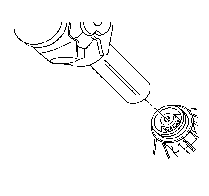
- Install the propeller
shaft into the transmission.
- Ensure that the slip joint splines are lubricated.
- Bottom the propeller shaft yoke in the transmission.
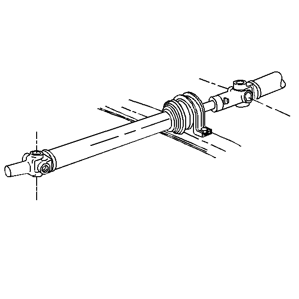
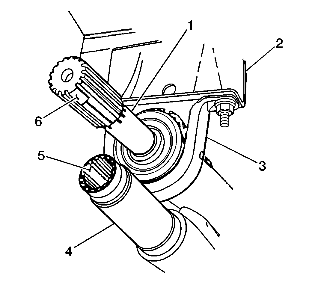
- Install the center bearing
support.
- Align the center bearing support 90 degrees to the propeller
shaft center lines.
Notice: Use the correct fastener in the correct location. Replacement fasteners
must be the correct part number for that application. Fasteners requiring
replacement or fasteners requiring the use of thread locking compound or sealant
are identified in the service procedure. Do not use paints, lubricants, or
corrosion inhibitors on fasteners or fastener joint surfaces unless specified.
These coatings affect fastener torque and joint clamping force and may damage
the fastener. Use the correct tightening sequence and specifications when
installing fasteners in order to avoid damage to parts and systems.
- Install the center
bearing support bolts.
Tighten
Tighten the center bearing support bolts to 35 N·m (26 lb ft).
- Install the slip yoke
(4) by aligning the missing tooth (5) with the bridged tooth (6) on the splined
shaft (1).
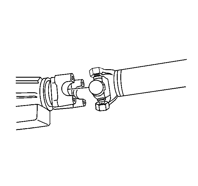
- Support the propeller shaft.
- Ensure the slip yoke ears are horizontal.
- Align the reference marks and install the propeller shaft to the
rear differential yoke.
- Install the retainers.
- Install the bolts.
Tighten
Tighten the bolts to 20 N·m (15 lb ft).
- Inspect for proper joint fit.
- Lubricate the center slip joint on two-piece shaft.
