Brake Caliper Replacement Rear
Removal Procedure
- Remove two-thirds of the brake fluid from the master cylinder.
- Raise the vehicle.
- Support the vehicle with safety stands.
- Mark the relationship between the wheel and the hub.
- Remove the tire and the wheel assembly. Refer to Tire and Wheel Removal and Installation in Wheels and Tires.
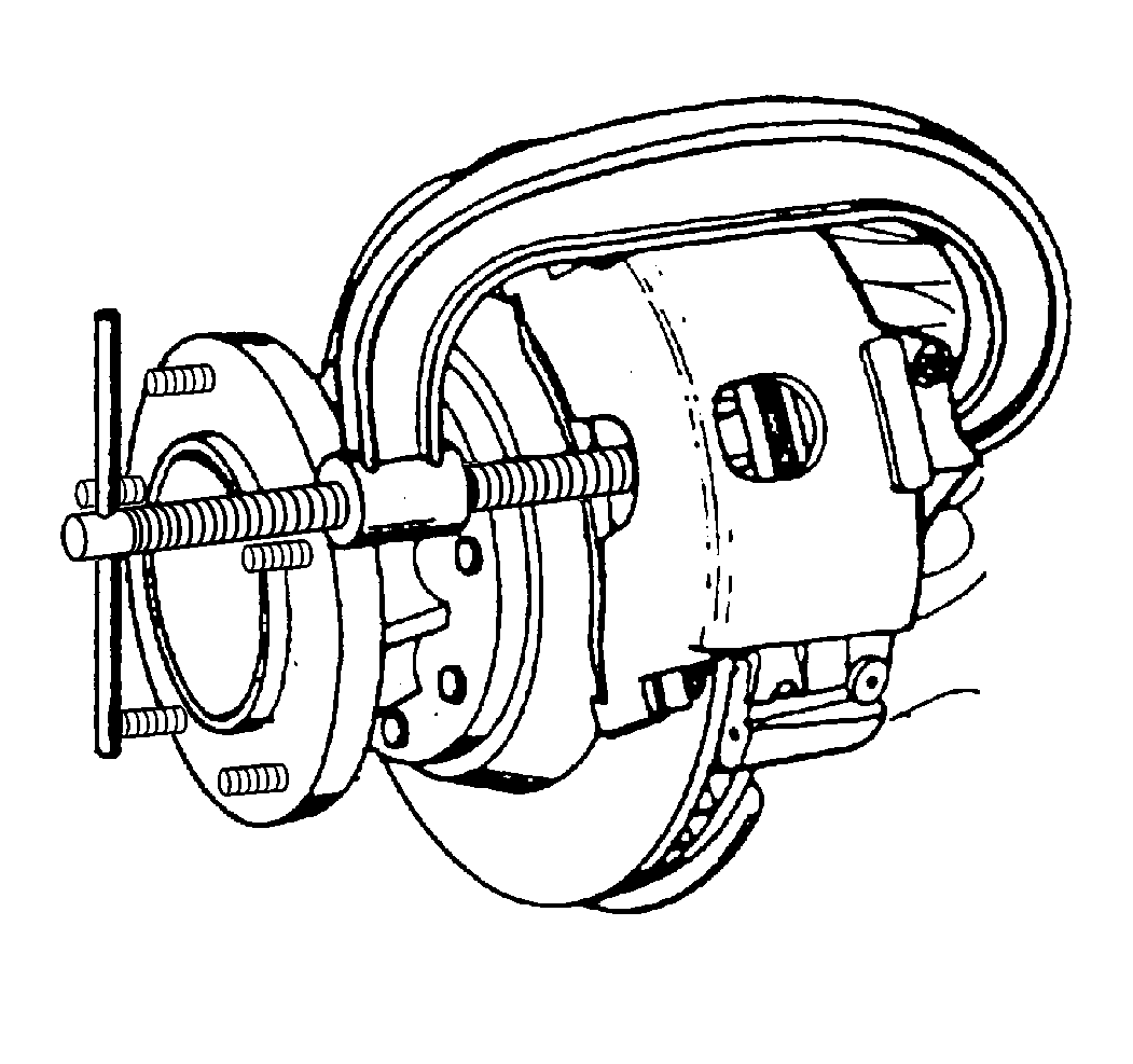
- Position a C-clamp and tighten it until the piston bottoms in the bore.
- Remove the C-clamp.
- Remove the brake hose. Refer to Brake Pipe Replacement in Hydraulic Brakes.
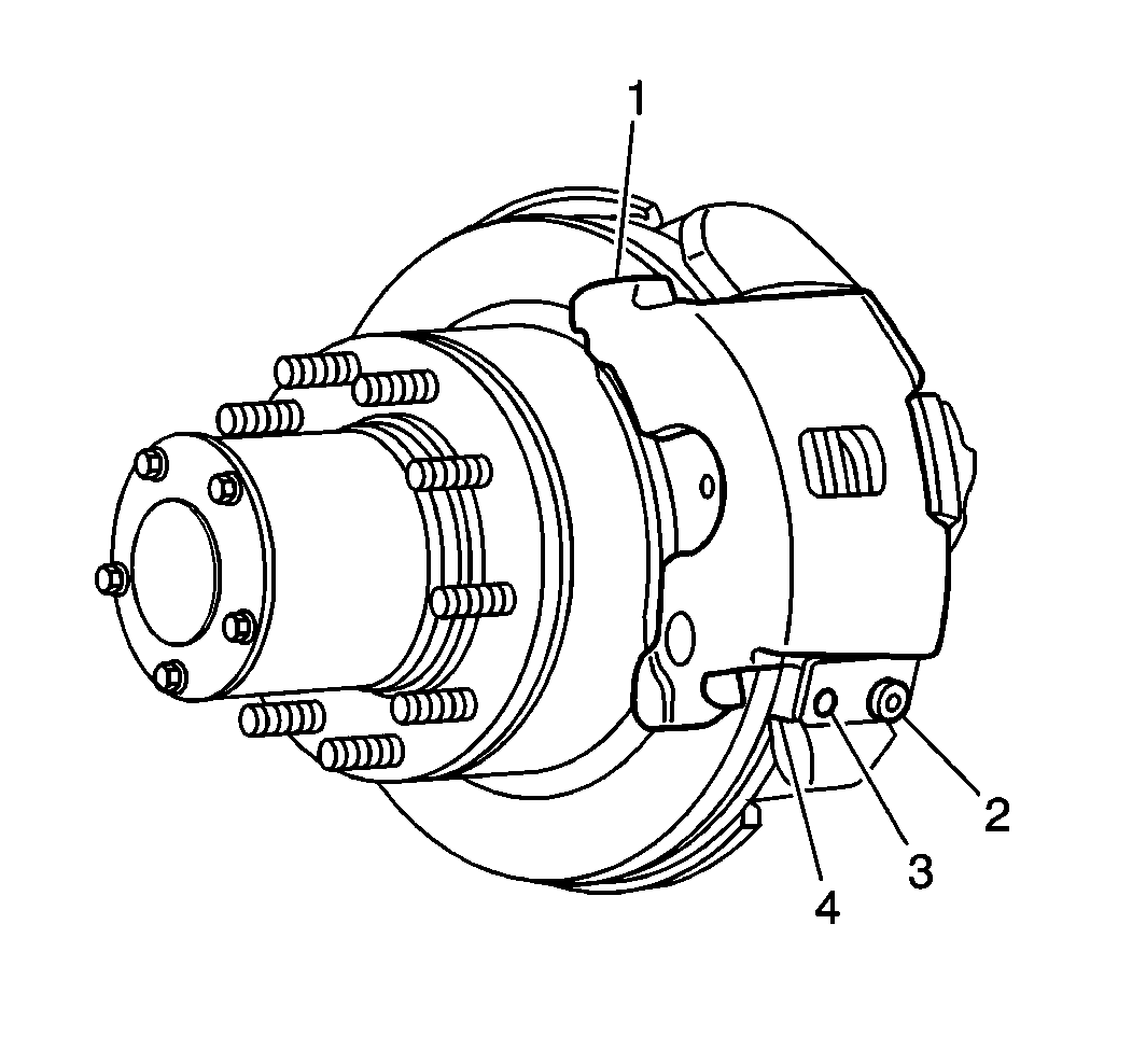
- Remove the bolt (2).
- Remove the support key (3) and the spring (4).
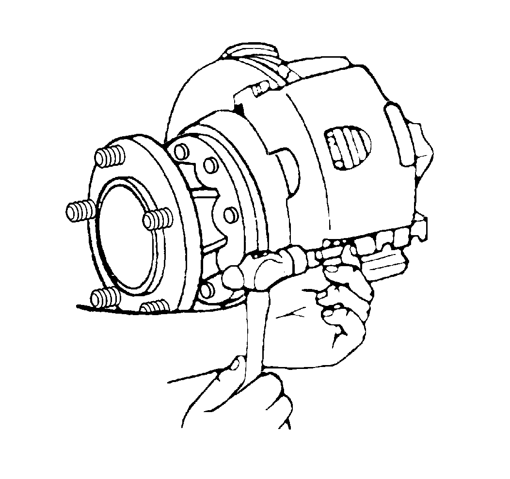
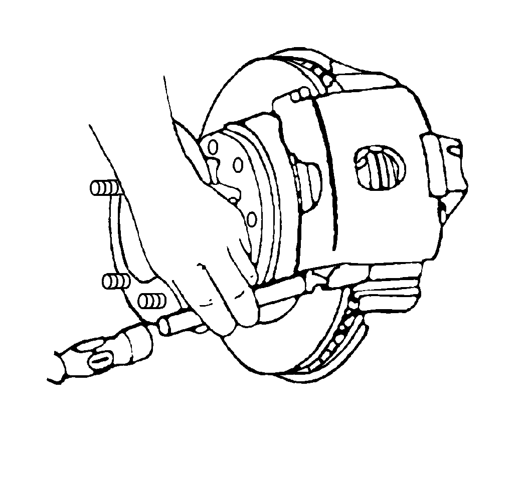
- Drive out the support key using a brass punch and a hammer.
- Remove the caliper assembly (1).
- Inspect the inside of the caliper assembly for signs of fluid leakage. Refer to Brake Caliper Overhaul if any leakage is detected.
- Use a wire brush to remove any corrosion from the machined surfaces of the anchor plate and the caliper.

Installation Procedure
- Lubricate the caliper and the anchor plate sliding surfaces with Shell Aeroshell® Grade 5 lubricant or equivalent.
- Install the caliper assembly (1).
- Install the spring (4) and the support key (3).
- Drive the support key in place using a brass punch and a hammer.
- Install the bolt (2). The boss on the bolt must fit into the circular cutout in the key.
- Install the brake hose.
- Bleed the system. Refer to Hydraulic Brake System Bleeding in Hydraulic Brakes.
- Install the tire and the wheel assembly. Refer to Tire and Wheel Removal and Installation in Tires and Wheels .
- Lower the vehicle.
Notice: Do not use NEVER SEIZE type products on the caliper V-ways and anchor plate guide way surfaces. These products are not lubricants and result in high caliper slide forces which can cause increased wear of the brake pads.


Notice: Use the correct fastener in the correct location. Replacement fasteners must be the correct part number for that application. Fasteners requiring replacement or fasteners requiring the use of thread locking compound or sealant are identified in the service procedure. Do not use paints, lubricants, or corrosion inhibitors on fasteners or fastener joint surfaces unless specified. These coatings affect fastener torque and joint clamping force and may damage the fastener. Use the correct tightening sequence and specifications when installing fasteners in order to avoid damage to parts and systems.
Tighten
Tighten the bolt to 20 N·m (15 lb ft).
Notice: Make sure the brake hose is not twisted or kinked after installation. Damage to the hose could result.
Tighten
Tighten the brake hose to 45 N·m (33 lb ft).
Important: Pump the brake pedal until it is firm before moving the vehicle. Check the brake fluid level in the master cylinder after pumping the brakes.
Brake Caliper Replacement Front Delco
Removal Procedure
- Remove two-thirds of the brake fluid from the master cylinder.
- Raise the vehicle.
- Support the vehicle with safety stands.
- Remove the tire and the wheel. Refer to Tire and Wheel Removal and Installation in Tires and Wheels. Reinstall two lug nuts to retain motor on K models below 3646.6 kg (8050 lbs) GVW.
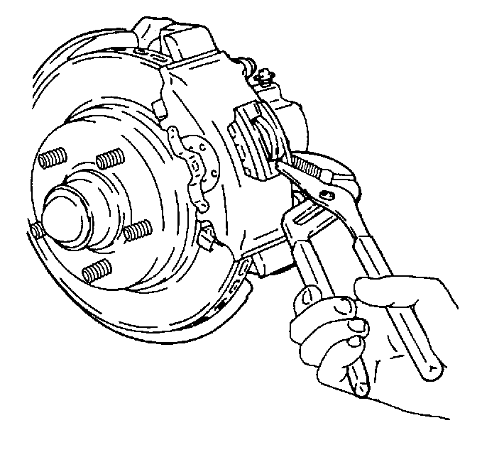
- Compress the piston using adjustable pliers over the inboard lining tab and the caliper housing flange.
- Remove the brake hose from the caliper by removing the inlet fitting bolt.
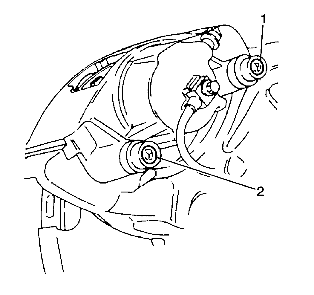
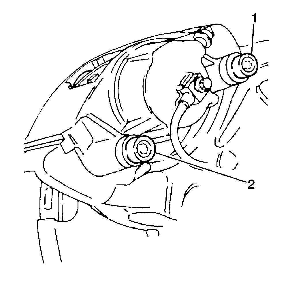
- Remove the mounting bolts (1), (2).
- Remove the bolt boots (1), (2).
- Remove the caliper.
- Remove the bushings.
- Inspect the mounting bolt and the sleeve assemblies for corrosion. Replace any corroded parts. Do not attempt to polish away any corrosion.
- Inspect the bolt boots for any nicks, cuts, or corrosion. Replace any damaged parts.
| • | Inspect the inside of the caliper assembly fpr signs of fluid leakage. Refer to Brake Caliper Overhaul if any leakage is detected. |
| • | Remove the mounting bolt seals if they were used. |
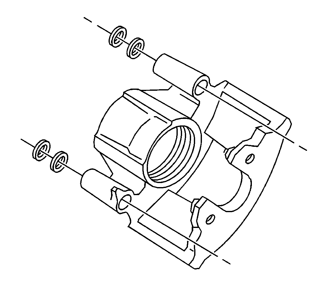
Important: Clean the caliper assembly and install a new brake hardware kit. Replace the brake hardware kit with each removal from the rotor.
Installation Procedure
- Install the new bushings and the bolt seals.
- Lubricate the bushings and the mounting bolt seals with GM P/N 18010909 or the equivalent.
- Install the new bolt boots (1), (2).
- Install the caliper.
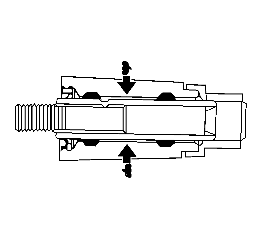
- Fill both housing cavities between the bushings with GM P/N 18010909 or the equivalent.
- Install the mounting bolt and the sleeve assemblies.
- Connect the brake hose to the caliper.
- Measure the clearance between the caliper and the bracket stops.


Notice: Use the correct fastener in the correct location. Replacement fasteners must be the correct part number for that application. Fasteners requiring replacement or fasteners requiring the use of thread locking compound or sealant are identified in the service procedure. Do not use paints, lubricants, or corrosion inhibitors on fasteners or fastener joint surfaces unless specified. These coatings affect fastener torque and joint clamping force and may damage the fastener. Use the correct tightening sequence and specifications when installing fasteners in order to avoid damage to parts and systems.
Tighten
Tighten the bolt to 51 N·m (38 lb ft). The
bolts boots must remain secure after tightening the bolts.
Tighten
Tighten the brake hose bolt to 45 N·m (33 lb ft).
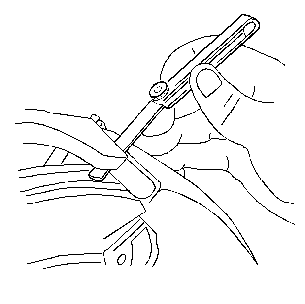
| • | If necessary, remove the caliper and file the ends of the bracket to obtain a 0.26 to 0.60 mm (0.010 to 0.024 in) total clearance. |
| • | Measure the clearances individually and then add them together. |
| • | Install the tire and the wheel. |
| Important: Pump the brake pedal until it is firm before moving the vehicle. Check the fluid level in the master cylinder after pumping the brakes. |
Brake Caliper Replacement Front Bendix
Removal Procedure
- Remove two-thirds of the brake fluid from the master cylinder.
- Raise the vehicle.
- Support the vehicle with safety stands.
- Mark the relationship between the wheel and the hub.
- Remove the tire and the wheel. Refer to Tire and Wheel Removal and Installation in Tires and Wheels.
- Position a C-clamp and tighten until the piston bottoms in the bore.
- Remove the C-clamp.
- Remove the brake hose.
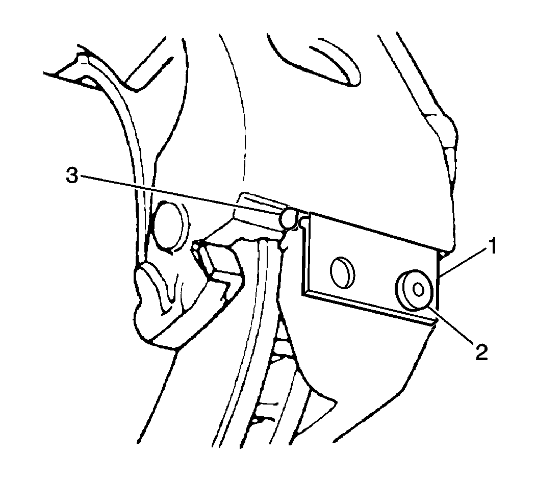
- Remove the bolt (2).
- Remove the support key and the spring using a brass punch and a hammer to drive out the support key.
- Remove the caliper assembly.
- Inspect the inside of the caliper assembly for signs of fluid leakage. Refer to Brake Caliper Overhaul if any leakage is detected.
- Use a wire brush to remove any corrosion from the machined surfaces of the anchor plate and the caliper.


Installation Procedure
- Lubricate the caliper and the anchor plate sliding surfaces with Shell Aeroshell® #5 or the equivalent.
- Install the caliper assembly.
- Install the spring and the support key using a brass punch and a hammer to drive the support key into place.
- Install the caliper lock mounting bolt (2). The boss on the bolt must fit into the circular cutout in the key.
- Install the brake hose.
- Bleed the brake system. Refer to Hydraulic Brake System Bleeding in Hydraulic Brakes.
- Install the tire and the wheel. Refer to Tire and Wheel Removal and Installation in Tires and Wheels.
- Lower the vehicle.
Notice: Make sure the brake hose is not twisted or kinked after installation. Damage to the hose could result.
Notice: Do not use NEVER SEIZE type products on the caliper V-ways and anchor plate guide way surfaces. These products are not lubricants and result in high caliper slide forces which can cause increased wear of the brake pads.


Notice: Use the correct fastener in the correct location. Replacement fasteners must be the correct part number for that application. Fasteners requiring replacement or fasteners requiring the use of thread locking compound or sealant are identified in the service procedure. Do not use paints, lubricants, or corrosion inhibitors on fasteners or fastener joint surfaces unless specified. These coatings affect fastener torque and joint clamping force and may damage the fastener. Use the correct tightening sequence and specifications when installing fasteners in order to avoid damage to parts and systems.
Tighten
Tighten the bolts to 20 N·m (15 lb ft).
Tighten
Tighten the brake hose bolt to 45 N·m (33 lb ft).
