Wheel Cylinder Replacement Leading/Trailing Drum Brakes
Removal Procedure
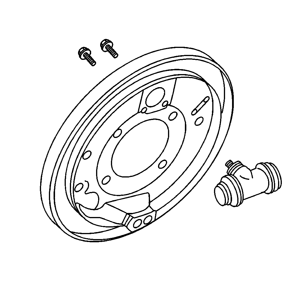
- Remove the shoe and linings. Refer to Brake Lining Replacement .
- Clean the dirt and foreign material from around the wheel cylinder.
- Remove the inlet pipe. Plug the pipe to prevent fluid loss and contamination.
- Remove the bolts.
- Remove the wheel cylinder.
Installation Procedure
- Install the wheel cylinder.
- Install the bolts.
- Install the inlet pipe.
- Install the shoes and linings. Refer to Brake Lining Replacement .
- Bleed the brake system. Refer to Hydraulic Brake System Bleeding .

Notice: Use the correct fastener in the correct location. Replacement fasteners must be the correct part number for that application. Fasteners requiring replacement or fasteners requiring the use of thread locking compound or sealant are identified in the service procedure. Do not use paints, lubricants, or corrosion inhibitors on fasteners or fastener joint surfaces unless specified. These coatings affect fastener torque and joint clamping force and may damage the fastener. Use the correct tightening sequence and specifications when installing fasteners in order to avoid damage to parts and systems.
Tighten
Tighten the bolts to 20 N·m (15 lb ft).

Tighten
Tighten the fitting to 17 N·m (13 lb ft).
Wheel Cylinder Replacement Components-Leading/Trailing
Removal Procedure
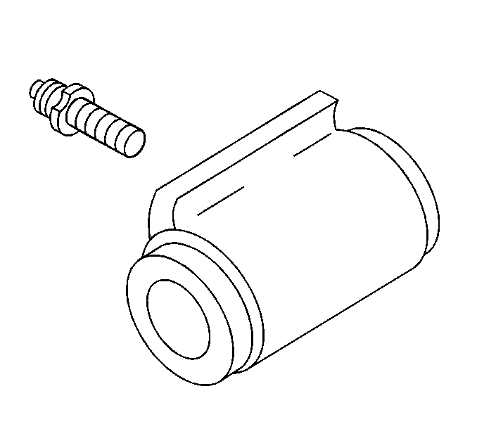
- Remove the bleeder valve.
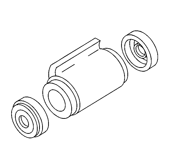
- Remove the boots.
- Remove the pistons.
- Remove the seals.
- Remove the spring assembly.
- Inspect the cylinder bore for scoring and corrosion.
- Inspect the spring assembly for signs of discoloration due to heat. Replace if necessary.
- Clean the inside of the cylinder bore with a crocus cloth. If the bore is still scored, replace the wheel cylinder.
- Clean the cylinder bore with clean brake fluid.
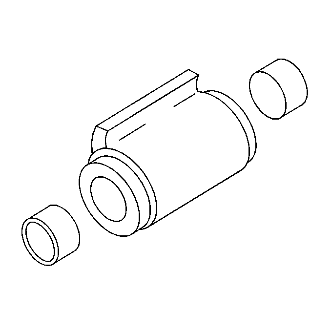
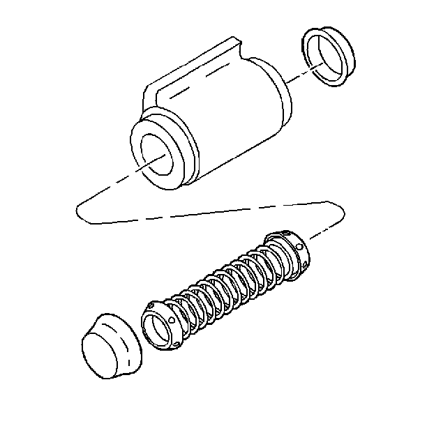
Installation Procedure
- Lubricate the pistons, seals, and cylinder bore with clean brake fluid.
- Install the spring assembly.
- Install the seals.
- Install the pistons.
- Install the boots.
- Install the bleeder valve.


Notice: Use the correct fastener in the correct location. Replacement fasteners must be the correct part number for that application. Fasteners requiring replacement or fasteners requiring the use of thread locking compound or sealant are identified in the service procedure. Do not use paints, lubricants, or corrosion inhibitors on fasteners or fastener joint surfaces unless specified. These coatings affect fastener torque and joint clamping force and may damage the fastener. Use the correct tightening sequence and specifications when installing fasteners in order to avoid damage to parts and systems.
Tighten
Tighten the bleeder valve to 13 N·m (110 lb in).
Wheel Cylinder Replacement Duo-Servo Drum Brakes
Removal Procedure
- Remove the linings. Refer to Brake Lining Replacement .
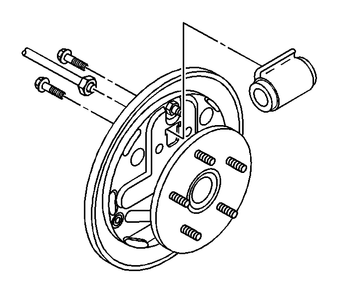
- Disconnect the brake pipe from the rear of the master cylinder.
- Remove the bolts.
- Remove the wheel cylinder.
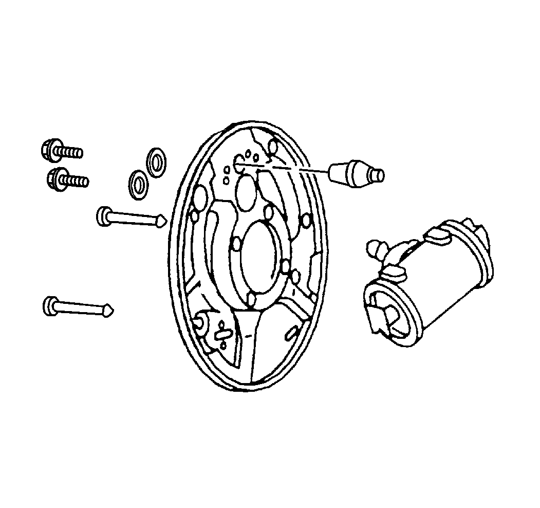
Installation Procedure
- Install the wheel cylinder.
- Install the bolts.
- Install the brake pipe.
- Install the linings. Refer to Brake Lining Replacement .

Notice: Use the correct fastener in the correct location. Replacement fasteners must be the correct part number for that application. Fasteners requiring replacement or fasteners requiring the use of thread locking compound or sealant are identified in the service procedure. Do not use paints, lubricants, or corrosion inhibitors on fasteners or fastener joint surfaces unless specified. These coatings affect fastener torque and joint clamping force and may damage the fastener. Use the correct tightening sequence and specifications when installing fasteners in order to avoid damage to parts and systems.
Tighten
Tighten the bolts to 25 N·m (18 lb ft).
Tighten
Tighten the brake pipe fitting to 17 N·m (13 lb ft).
