Removal Procedure
Notice: Do not damage the MAF sensor screen. A damaged screen could restrict airflow and lead to a driveability concern.
- Disconnect the negative battery cable. Refer to Battery Negative Cable Disconnection and Connection in Engine Electrical.
- Relieve the fuel system pressure. Refer to the Fuel Pressure Relief .
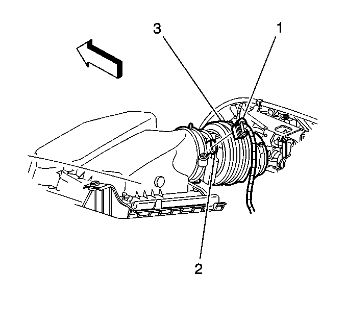
- Remove the mass air flow/intake air temperature (MAF/IAT) sensor electrical connector (1) from the MAF/IAT sensor (2).
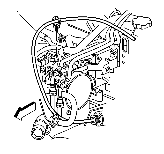
- Remove the air cleaner intake duct assembly (3).
- Remove the positive crankcase ventilation (PCV) valve fresh air tube.
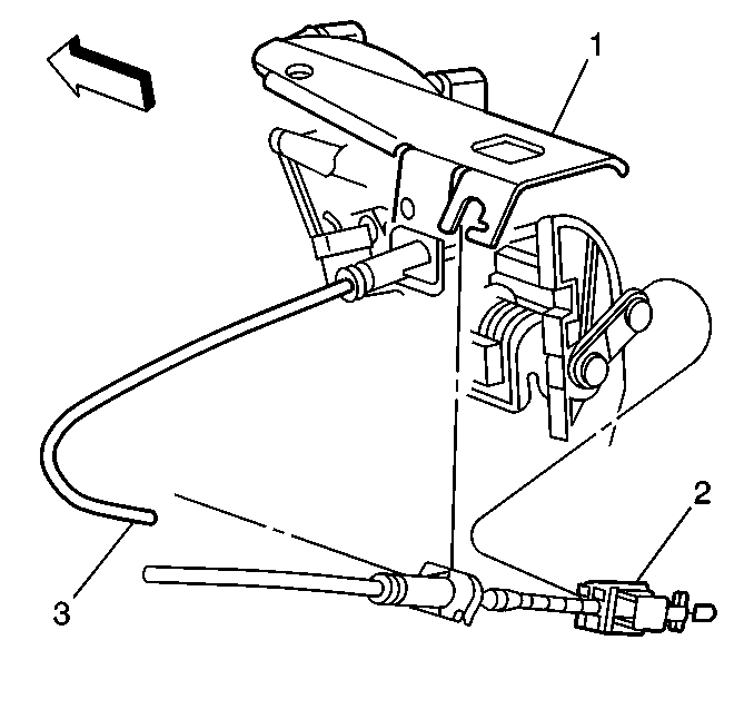
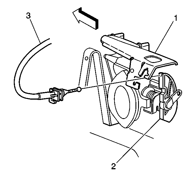
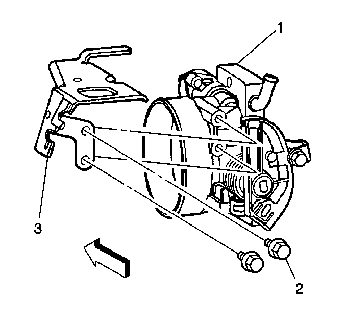
- Remove the cruise control cable (2) from accelerator controls cable bracket (1).
- Remove the accelerator cable (3) from accelerator controls cable bracket (1).
- Remove the cruise control cable (2) from throttle body lever.
- Remove the accelerator control cable (3) from throttle body lever (2).
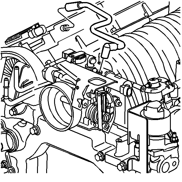
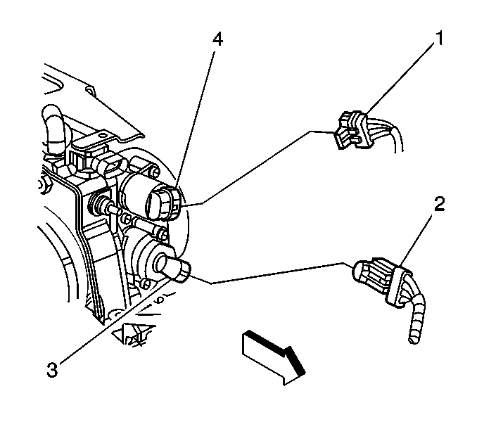
- Remove the idle air control (IAC) valve electrical connector (1) from the IAC valve (4).
- Remove the throttle position (TP) sensor electrical connector (2) from the TP sensor (3).
- Remove the transaxle shift cable (1) clip from the accelerator controls cable bracket.
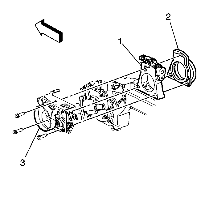
- Remove the throttle body (3) bolts from the water crossover (1). Discard plenum duct (2).
- Remove the accelerator controls cable bracket bolts (2) from the accelerator controls cable bracket (3).
- Remove the accelerator controls cable bracket (3) from the throttle body (1).
Installation Procedure
Notice: Do not use a cleaner which contains methyl ethyl ketone. This extremely strong solvent may damage components and is not necessary for this type of cleaning.
Use a carburetor cleaner in order to remove deposits. Refer to the instructions provided with the cleaner.Notice: The outlet of the air cleaner assembly and the MAF sensor inlet duct must line up when completely installed. Misalignment may cause incorrect airflow readings resulting in MIL illumination or a driveability concern. An improperly installed inlet duct assembly or air cleaner assembly may cause misalignment.
Important: Do not reuse the old throttle body gasket or plenum duct.
- Install the accelerator cable bracket (3) to the throttle body (1).
- Install the accelerator cable bracket bolts (2) to the accelerator cable bracket (3).
- Position the new throttle body gasket on to the throttle body.
- Install bolts from the throttle body (3) to the water crossover (1) and new plenum duct (2).
- Install the IAC valve electrical connector (1) to the IAC valve (4).
- Install the TP sensor electrical connector (2) to the TP sensor (3).
- Install the accelerator control cable (3) to the throttle body lever (2).
- Install the cruise control cable (2) to the throttle body lever.
- Install the accelerator cable (3) to the accelerator controls cable bracket (1).
- Install the cruise control cable to accelerator controls cable bracket (1).
- Install the transaxle shift cable (1) clip to the accelerator controls cable bracket.
- Install the MAF/IAT sensor electrical connector (1) to the MAF/IAT sensor (2).
- Install the air cleaner intake duct assembly (3).
- Install the PCV valve fresh air tube.
- Install the negative battery cable. Refer to Battery Negative Cable Disconnection and Connection in Engine Electrical.
- Perform the TP sensor learn procedure.
Notice: Use the correct fastener in the correct location. Replacement fasteners must be the correct part number for that application. Fasteners requiring replacement or fasteners requiring the use of thread locking compound or sealant are identified in the service procedure. Do not use paints, lubricants, or corrosion inhibitors on fasteners or fastener joint surfaces unless specified. These coatings affect fastener torque and joint clamping force and may damage the fastener. Use the correct tightening sequence and specifications when installing fasteners in order to avoid damage to parts and systems.
Tighten
Tighten the bolts to 12 N·m (106 lb in).
Tighten
Tighten the bolts to 12 N·m (106 lb in).
Tighten
Tighten the air cleaner intake duct clamps to 3 N·m (27
lb in).
TP Sensor Learn Procedure
- Perform the IAC valve learn procedure
| 16.1. | Turn the ignition switch to the RUN/ON position. |
| 16.2. | Wait 1 minute. |
| 16.3. | Turn the ignition switch to the LOCK/OFF position. |
| 16.4. | Wait 15 seconds. |
IAC Valve Learn Procedure
| 17.1. | Start and idle the engine for 15 seconds. |
| 17.2. | Turn the ignition switch to the LOCK/OFF position. |
| 17.3. | Wait 15 seconds. |
| 17.4. | Restart the engine , and check for proper idle operation. |
