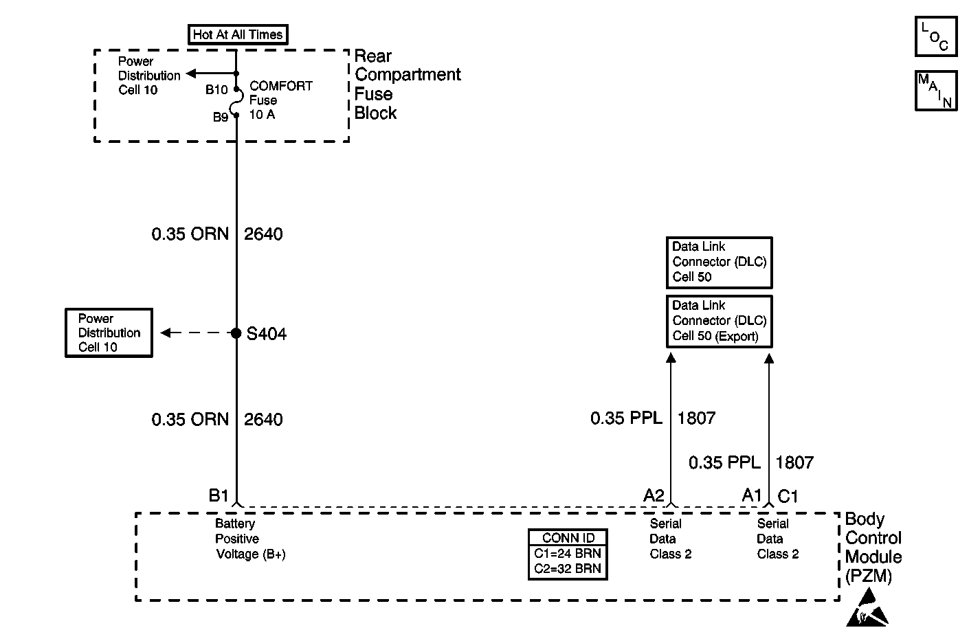
Circuit Description
Battery voltage is supplied to the body control module (PZM) at connector C1 terminal B1. While the PZM is awake the battery voltage at connector C1 terminal B3 is measured every 300 ms.
Conditions for Setting the DTC
The battery voltage measured at connector C1 terminal B1 is less than 9 volts for 4 monitoring cycles.
Action Taken When the DTC Sets
When DTC B1981 is current, class 2 loss of serial data DTCs will not set.
Conditions for Clearing the DTC
| • | The battery voltage is more than 9.5 volts in the next monitoring cycle. |
| • | A history code clears after 50 consecutive ignition cycles if the condition is no longer present. |
Diagnostic Aids
Use a scan tool in order to monitor the battery voltage display of several modules. If the displayed battery voltage is 9 volts or less, refer to Charging System Check in Engine Electrical.
Step | Action | Value(s) | Yes | No |
|---|---|---|---|---|
1 | Was the Body Control Module Diagnostic System Check performed? | Go to Step 2 | ||
2 |
Retrieve the instrument panel (IPC) DTCs? Is DTC B1983 current? | -- | Go to Charging System Check in Engine Electrical | Go to Step 3 |
3 |
Is the voltage within the specified range? | 10-15 V | Go to Step 4 | Go to Step 5 |
4 | Replace the PZM. Refer to Body Control Module Replacement . Is the repair complete? | -- | -- | |
5 | Repair the high resistance in CKT 2640 (ORN). Is the repair complete? | -- | -- |
