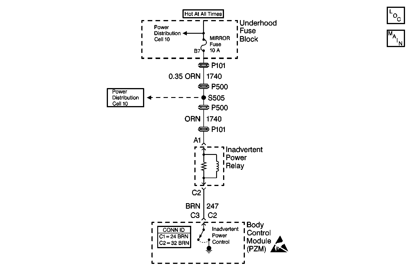
Circuit Description
The inadvertent power is commanded ON and OFF by the body control module (PZM) inadvertent power output by grounding the inadvertent power relay in connector C2 at terminal C3. The relay and the components powered through the relay are energized and supplied battery voltage.
Conditions for Setting the DTC
The inadvertent power relay is commanded ON or OFF and the PZM feed back does not match that of the commanded state for at least 2 seconds.
Action Taken When the DTC Sets
The PZM continues to command the requested state of the relay until the state is achieved or no longer necessary.
Conditions for Clearing the DTC
The PZM feedback matches that of the commanded state for at least 2 seconds.
| • | When the measurements are requested in this chart use J 39200 Digital Multimeter (DMM) with the correct terminal adapter from the J 35616 . |
| • | When a proper connection is requested, refer to Intermittents and Poor Connections Diagnosis in Wiring Systems. |
| • | When a wire, connector or terminal repair is requested, use the J-38125 . Refer to Wiring Repairs in Wiring Systems. |
Step | Action | Value(s) | Yes | No |
|---|---|---|---|---|
1 |
Do the lamps turn on? | -- | Go to Step 2 | Go to Step 3 |
2 |
Is the resistance less than or equal to the specified value? | 5 ohms | Go to Step 4 | Go to Step 5 |
3 |
Is battery voltage measured? | -- | Go to Step 6 | Go to Step 7 |
4 | Repair the short to ground in CKT 247 (BRN). Refer to Wiring Repairs in Wiring Systems. Is the repair complete? | -- | -- | |
5 | Replace the body control module. Refer to Body Control Module Replacement in Body Control System. Is the body control module replacement complete? | -- | -- | |
6 |
Is the resistance less than or equal to the specified value? | 5 ohms | Go to Step 8 | Go to Step 9 |
7 | Repair the open or short to ground in CKT 1740 (ORN). Refer to Wiring Repairs in Wiring Systems. Is the repair complete? | -- | -- | |
8 | Replace the inadvertent power relay. Is the relay replacement complete? | -- | -- | |
9 | Inspect for an open in CKT 247 (BRN). Refer to Testing for Continuity in Wiring Systems. Is CKT 247 OK? | -- | Go to Step 5 | Go to Step 10 |
10 | Repair the suspect wiring. Refer to Wiring Repairs in Wiring Systems. Is the repair complete? | -- | -- |
