Circuit Description
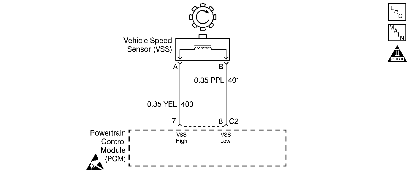
The Vehicle Speed Sensor (VSS) is a Permanent Magnet (PM) generator attached to the transmission case. The final drive assembly has a toothed wheel (VSS rotor). As the final drive assembly rotates, an AC voltage is induced and transmitted to the Powertrain Control Module (PCM). The PCM converts the AC voltage into a digital signal. The PCM uses the vehicle speed in order to determine shift timing, Torque Converter Clutch (TCC) apply and release, and gear ratio. The VSS voltage will vary from 0.5 volts AC at 100 RPM to more than 100 volts AC at 8000 RPM. The VSS resistance value is 1300-1950 ohms.
If the PCM detects a low vehicle speed and a high Input Shaft Speed sensor signal while in a drive range, then DTC P0502 sets. DTC P0502 is a Type B DTC.
Conditions for Setting the DTC
| • | No MAF DTCs P0101, P0102 or P0103. |
| • | No TP DTCs P0121, P0122 or P0123. |
| • | No A/T ISS DTCs P0716 or P0717. |
| • | No TFP Val. Position Sw. DTC P1810. |
| • | The transmission is not in Park, Neutral, or Reverse. |
| • | The delivered torque is greater than 109 N·m (80 lb ft). |
| • | The TP angle is greater than 12.8 degrees. |
| • | The input shaft speed is 2000 RPM or greater. |
| • | The vehicle speed is 8 km/h (5 mph) or less for 2 seconds. |
Action Taken When the DTC Sets
| • | The PCM illuminates the Malfunction Indicator Lamp (MIL). |
| • | SERVICE ENGINE SOON, SPEED SENSOR FAULT displays on the Driver Information Center (DIC). |
| • | The PCM commands default line pressure. |
| • | The PCM inhibits TCC engagement. |
| • | The PCM disables the cruise control. |
| • | The PCM disables steady state adapts. |
| • | The PCM disables upshift adapts. |
| • | The PCM calculates vehicle speed from the Automatic Transmission Input (Shaft) Speed sensor and commanded gear. |
| • | DTC P0502 is stored in the PCM history. |
Conditions for Clearing the MIL/DTC
| • | The PCM turns OFF the MIL after three consecutive trips without a failure reported. |
| • | A scan tool can clear the DTC from the PCM history. The PCM clears the DTC from the PCM history if the vehicle completes 40 warm-up cycles without a failure reported. |
| • | The PCM cancels the DTC default actions when the fault no longer exists and the ignition is OFF long enough in order to power down the PCM. |
Diagnostic Aids
| • | Inspect the wiring at the PCM, and the VSS 2-way connector for the following conditions: |
| - | A bent terminal |
| - | A backed out terminal |
| - | A damaged terminal |
| - | Poor terminal tension |
| - | A chafed wire |
| - | A broken wire inside the insulation |
| - | Moisture intrusion |
| • | When diagnosing for an intermittent short or open, massage the wiring harness while watching the test equipment for a change. |
| • | Check for Electromagnetic Interferences (EMI) induced on circuits 400 and 401 by a misrouted harness along spark plug wires. |
Test Description
The numbers below refer to the step numbers on the diagnostic table.
-
This step checks for DTCs and for a vehicle speed signal. It is important to record Freeze Frame and Failure Record information before proceeding further.
-
This step has the Scan Tool verify that the correct calibration is in the PCM.
-
This step tests for a resistance value greater than 1950 ohms which would indicate a possible open in circuit 400 or circuit 401.
-
This step verifies that the ohmmeter displays a value less than or equal to the specified VSS value. Resistance less than 1300 implies that the circuits are shorted together. Resistance within specification implies that circuit 400 or circuit 401 is a possible short to ground.
-
This step performs a resistance check on the VSS, if no opens, shorts to ground or shorts together were found on circuit 400 or circuit 401.
Step | Action | Value(s) | Yes | No | ||||
|---|---|---|---|---|---|---|---|---|
1 | Was the Powertrain On-Board Diagnostic (OBD) System Check performed? | -- | Go to Powertrain On Board Diagnostic (OBD) System Check in Engine Controls | |||||
Important: Before clearing the DTC(s), use the Scan Tool in order to record the Freeze Frame and Failure Records for reference. Using the Clear Info function will erase the stored Freeze Frame and Failure Records from the PCM. Notice: Support the lower control arms in the normal horizontal position in order to avoid damage to the drive axles. Do not operate the vehicle in gear with the wheels hanging down at full travel. With the drive wheels rotating, does the Transmission OSS RPM increase when the wheel speed increases? | -- | Go to Diagnostic Aids | ||||||
3 |
Important: Place the gear select lever in the Neutral position before rotating the wheel. Is the voltage greater than the specified value? | 0.5 V | ||||||
Use the Scan Tool in order to check for the most current calibration ID. Does the ID number match? | -- | |||||||
5 | Update the PCM with the latest calibration. Refer to Powertrain Control Module Replacement/Programming in Engine Controls. Is the calibration update complete? | -- | -- | |||||
Connect the J 39200 DMM from terminal 7 to terminal 8 of the PCM connector and measure the resistance. Is the resistance greater than the specified value? | 1950ohms | |||||||
7 |
Refer to General Electrical Diagnosis in Wiring Systems. Did you find and correct the condition? | -- | ||||||
Is the resistance within (or less than) the specified range? | 1300-1950 ohms | |||||||
9 |
Refer to General Electrical Diagnosis in Wiring Systems. Did you find and correct the condition? | -- | ||||||
Is the resistance within the specified range? | 1300-1950 ohms | |||||||
11 | Replace the Vehicle Speed Sensor. Refer to Vehicle Speed Sensor Replacement . Is the replacement complete? | -- | -- | |||||
12 | Replace the PCM. Refer to Powertrain Control Module Replacement/Programming in Engine Controls. Is the replacement complete? | -- | -- | |||||
13 | In order to verify your repair, perform the following procedure:
Has the test run and passed? | -- | System OK |
