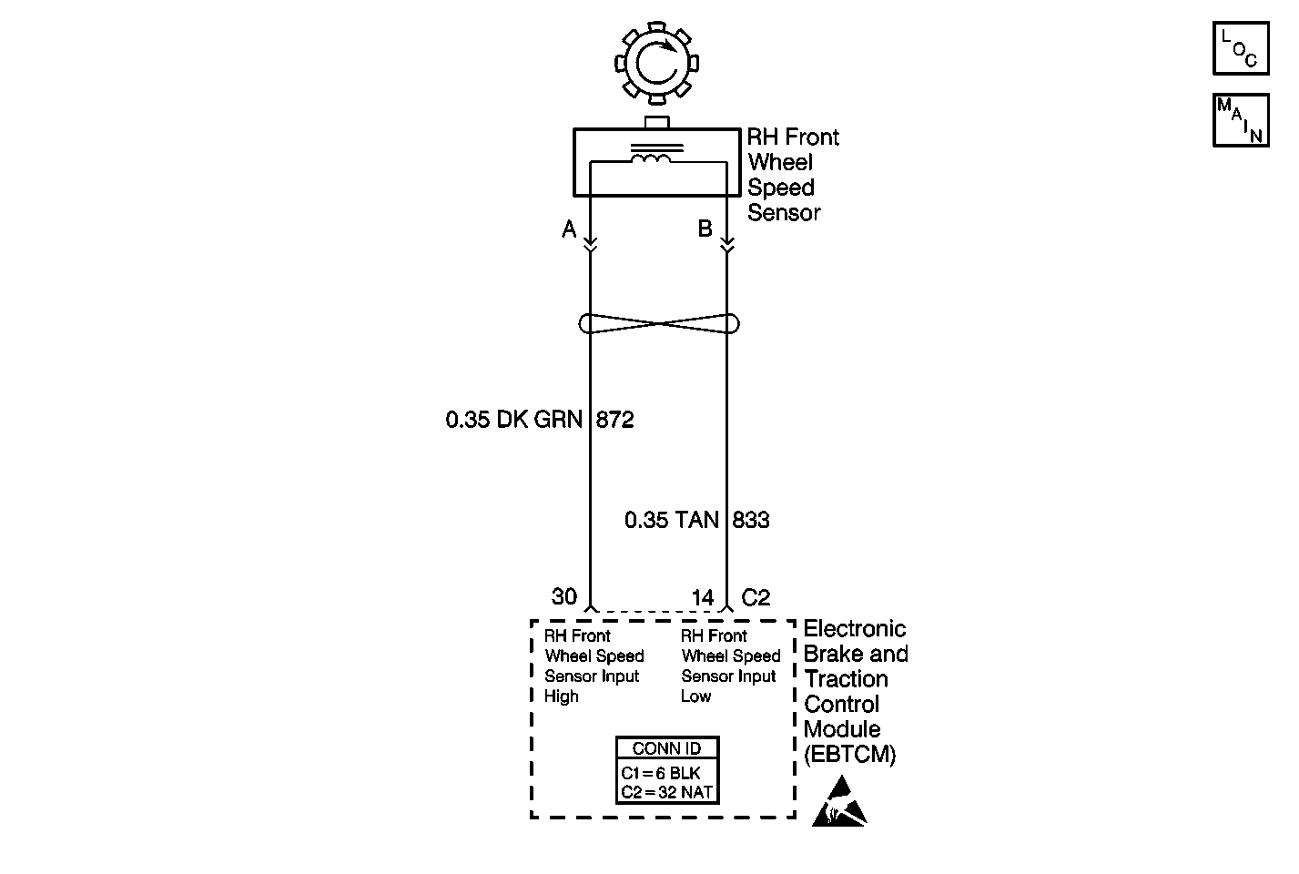
Circuit Description
The wheel speed sensor used on this vehicle is a single point magnetic pickup. This sensor produces an AC signal that the EBTCM uses the frequency from to calculate the wheel speed.
Conditions for Setting the DTC
The DTC sets if all of the following occur:
| • | The brake pedal is not depressed. |
| • | No wheel speed sensor hardware DTCs are present. |
| • | The EBTCM sees a wheel speed variation of more than 14 Km/h (9 mph) for 2.5 seconds. |
Action Taken When the DTC Sets
| • | A malfunction DTC is stored. |
| • | The ABS/TCS/Stabilitrak® is disabled. |
| • | The ABS indicator is turned ON. |
| • | The TRACTION CONTROL indicator is turned ON. |
| • | The DIC displays the SERVICE STABILITY SYS message. |
Conditions for Clearing the DTC
| • | The condition for DTC is no longer present and you used scan tool Clear DTCs function. |
| • | The condition for DTC is no longer present and you used the On-Board Clear DTCs function. |
| • | The EBTCM does not detect the DTC in 50 drive cycles. |
Diagnostic Aids
| • | Perform a thorough inspection of the wiring and the connectors. Failure to carefully and fully inspect wiring and connectors may result in misdiagnosis, causing part replacement with reappearance of the malfunction. |
| • | An intermittent malfunction may be caused by poor connections, broken insulation, or a wire that is broken inside the insulation. |
| • | If an intermittent malfunction exists, refer to Intermittents and Poor Connections . |
Test Description
The numbers below refer to step numbers on the diagnostic table.
Step | Action | Value(s) | Yes | No |
|---|---|---|---|---|
1 | Was the Diagnostic System Check performed? | -- | Go to Step 2 | Go to Diagnostic System Check |
2 |
Is physical damage of the sensor evident? | -- | Go to Step 7 | Go to Step 3 |
Is the resistance within the specified range? | 850-1350 ohms | Go to Step 4 | Go to Step 7 | |
4 |
Is the AC voltage greater than the specified value? | 100 mV | Go to Step 5 | Go to Step 7 |
Is the resistance equal to the specified value? | OL (infinite) | Go to Step 6 | Go to Step 8 | |
6 |
Does the DTC reset as a current DTC? | -- | Go to Step 9 | Go to Diagnostic System Check |
7 | Replace the wheel speed sensor. Refer to Front Wheel Bearing and Hub Replacement in Front Suspension. Did you complete the repair? | -- | Go to Step 10 | -- |
8 | Repair a short between CKT 833 and CKT 872. Refer to Wiring Repairs in Wiring Systems. Did you complete the repair? | -- | Go to Step 10 | -- |
9 | Replace the EBTCM. Refer to Electronic Brake Control Module Replacement . Did you complete the repair? | -- | Go to Step 10 | -- |
10 | Carefully test drive vehicle above 24 Km/h (15 mph) while monitoring a scan tool for at least 30 seconds. Does the DTC set as a current DTC? | -- | Go to Step 2 | Go to Diagnostic System Check |
