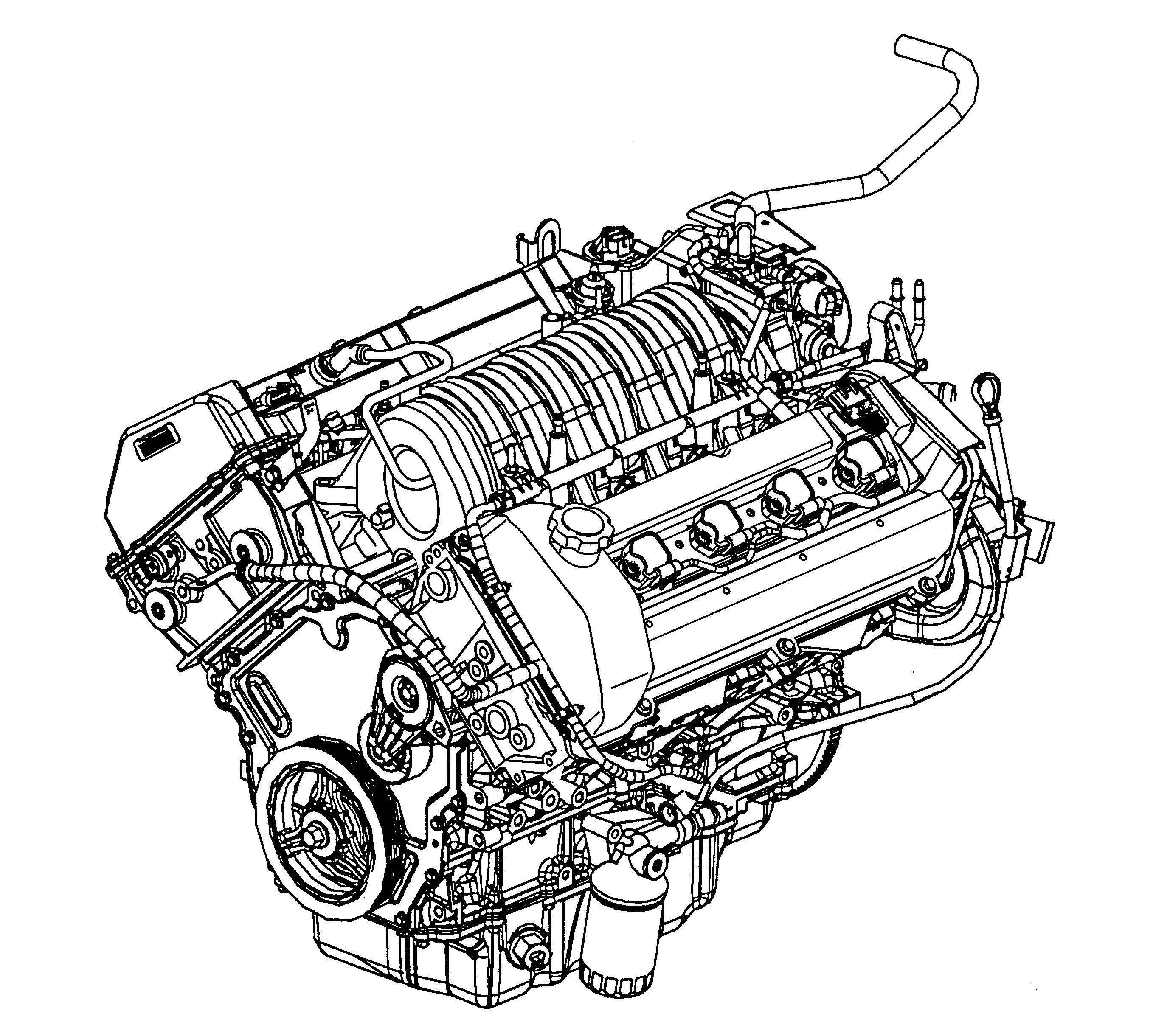
Northstar LD8/L37 - Front View
Northstar LD8/L37 - Rear View
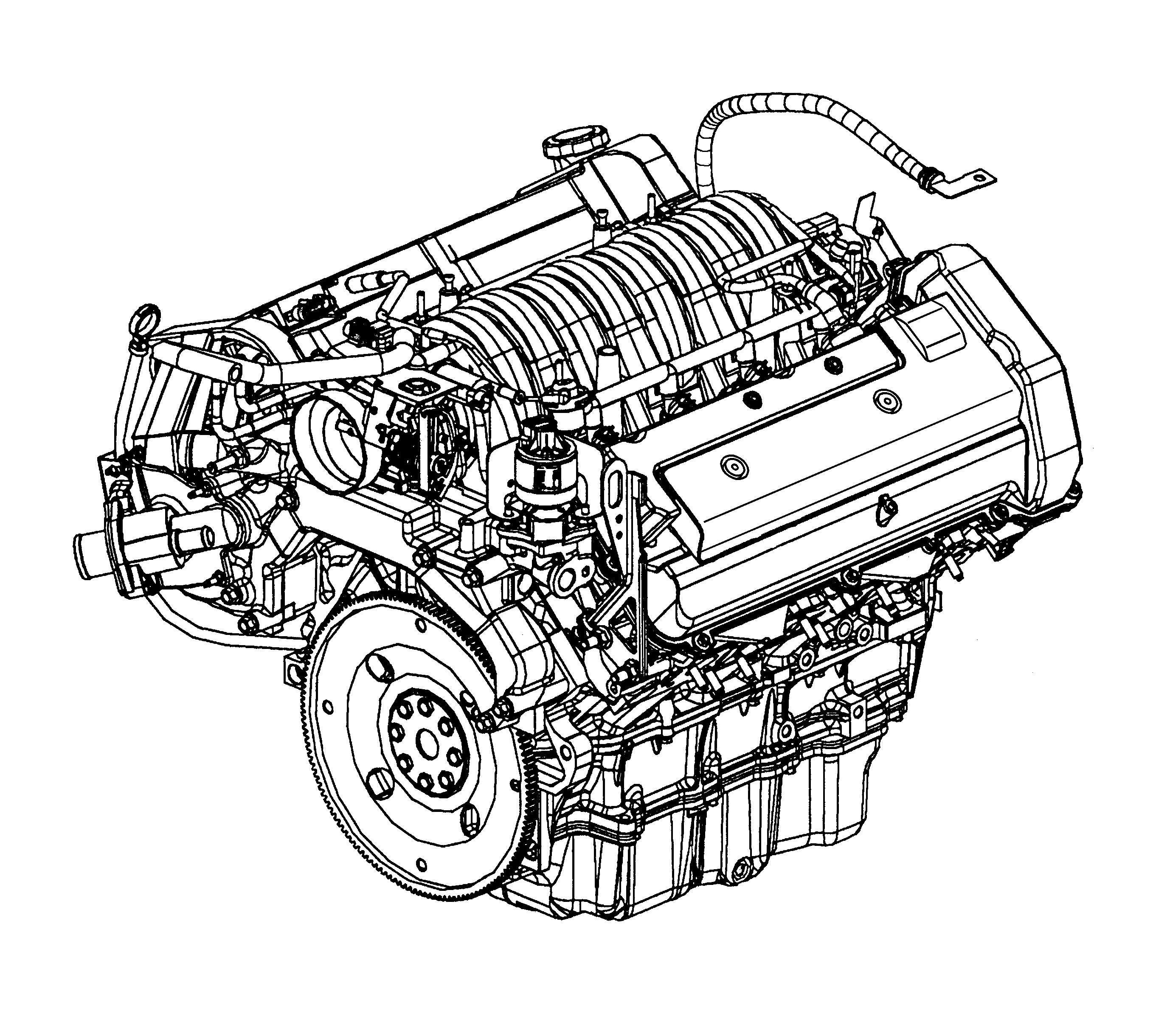
The Northstar V8 VIN Code 9 or Y is a 4.6L (279 cu in) engine incorporating 2 intake and 2 exhaust valves per cylinder with individual cylinder head mounted camshafts for intake and exhaust functions (DOHC). The cylinder bore diameter is 93 mm (3.43 in) and the piston stroke is 84 mm (3.31 in). The cylinders are arranged in 2 banks of 4 with a 90 degrees included angle. The left (front) bank of cylinders are number 2-4-6-8 and the right (rear) bank cylinders are 1-3-5-7. Engine firing order is 1-2-7-3-4-5-6-8.
Crankcase
The cylinder block is constructed of aluminum alloy by the die casting method and is constructed of 2 sections, an upper and a lower crankcase, split at the crankshaft center line. The grey cast iron cylinder liners are cast with the upper crankcase. The upper and lower crankcase sections are held in alignment by 4 dowel pins. Once machined, the sections must be kept together as a set. Sealing between the crankcase halves consists of a silicone rubber seal and a bead of anaerobic sealant along each side. Since the lower crankcase contains the lower main bearings, this casting adds to the structural rigidity of the engine assembly. Both upper and lower crankcases incorporate oil drain back passages isolated from the crankcase. These passages provide a direct path from the cylinder heads to the oil pan in order to prevent the needless aeration of the oil through contact with the rotating components.
Crankshaft
All designs use 5 main bearings. Crankshaft thrust is taken by the number three main bearing. The position sensor, also known as the reluctor wheel, is cast integrally with the crankshaft. The crankshaft is internally balanced and incorporates a one piece rear seal. A rolled fillet radius is incorporated on all bearing journals to improve fatigue strength.
Connecting Rods and Pistons
The connecting rod piston pin bore has an approximately 23 mm (0.906 in) diameter. The piston pin has an approximately 23 mm (0.906 in) diameter. The piston pin bore has an approximately 23 mm (0.906 in) diameter. The connecting rods are forged steel and have full floating piston pins. These pins are slip fit in the bronze bushed rods and are retained in the piston by round wire retainers. The cast aluminum pistons use 2 low tension compression rings and one multi-piece oil ring. The top compression ring is nitrided steel. The second compression ring is coated cast iron. The oil ring is a 3 piece side seal type ring which incorporates a steel expander and 2 chrome plated steel rails. The piston also incorporates a new anti-friction, anti-scuffing, protective coating applied to the skirt of the piston.
Camshaft Drive System
The 4 overhead camshafts are driven by 3 separate fine pitch chains. The primary drive chain connects the crankshaft with the intermediate shaft and sprocket located directly above the crankshaft behind the engine front cover. Each camshaft drive chain connects the intermediate sprocket with both intake and exhaust cams in the cylinder head. Two camshaft drive chains are used; one for each cylinder head. Each of the chains incorporates a hydraulic tensioner to minimize chain noise and provide accurate valve action by keeping slack out of the chain and continuously adjusting for chain wear. This is accomplished by providing engine oil pressure to each tensioner forcing a nylon pad into mesh with the slack side of the chain. As the chain stretches from wear, a ratchet mechanism inside the tensioner prevents the nylon pad from retracting when the engine is turned off and engine oil pressure ceases.
Cylinder Heads
The cylinder heads are semi permanent mold cast aluminum with powdered metal valve seat inserts and valve guides. Two 36.2 mm (1.425 in) intake valves and two 29 mm (1.141 in) exhaust valves are actuated by roller finger followers pivoting on a stationary hydraulic lash adjuster (SHLA). Separate intake and exhaust camshafts are supported by 5 bearings machined into the cylinder head with camshaft thrust taken by the first bearing (the left hand intake cam has an additional bearing to accommodate the water pump drive). The combustion chamber is roughly in the shape of a clover leaf with a nominal volume of 56.5 cc (3.448 cubic inch) and a centrally located spark plug.
Engine Cooling System
The left hand cylinder head intake camshaft extends outside the left hand cam cover providing drive mechanism for the coolant pump. A removable one piece lip seal prevents oil leakage around the camshaft. A drive pulley is pressed onto the end of the camshaft and provides drive for the engine coolant pump using a small multi rib drive belt and tensioner mechanism. The coolant pump assembly is located inside the water crossover casting. The water crossover distributes coolant to the cylinder block and collects it from the cylinder head for delivery to the radiator. The water crossover also provides important functions for the exhaust gas recirculation (EGR) system.
Induction System
The induction manifold is a plastic, lost core casting with a removable plastic sight shield cover.
Right and Left Bank Designation
Right hand (RH) and left hand (LH) designations through the engine mechanical On-Vehicle Service section are viewed from the rear of the engine, left side of the vehicle. In certain cases where a location with respect to the vehicle is required, it will be referred to as right side or left side as viewed from inside the vehicle.
