Removal Procedure
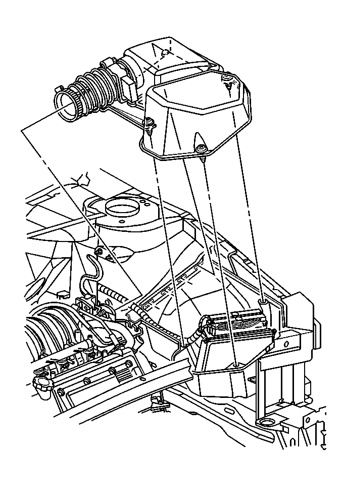
- Disconnect the mass air flow/intake air temperature (MAF/IAT) sensor electrical connector.
- Loosen the intake air duct clamp at the throttle body.
- Remove the bolts retaining the upper housing cover to the lower housing.
- Remove the upper housing cover and air intake duct from the throttle body and lower housing.
- Remove the powertrain control module (PCM) and connector assembly from the lower housing.
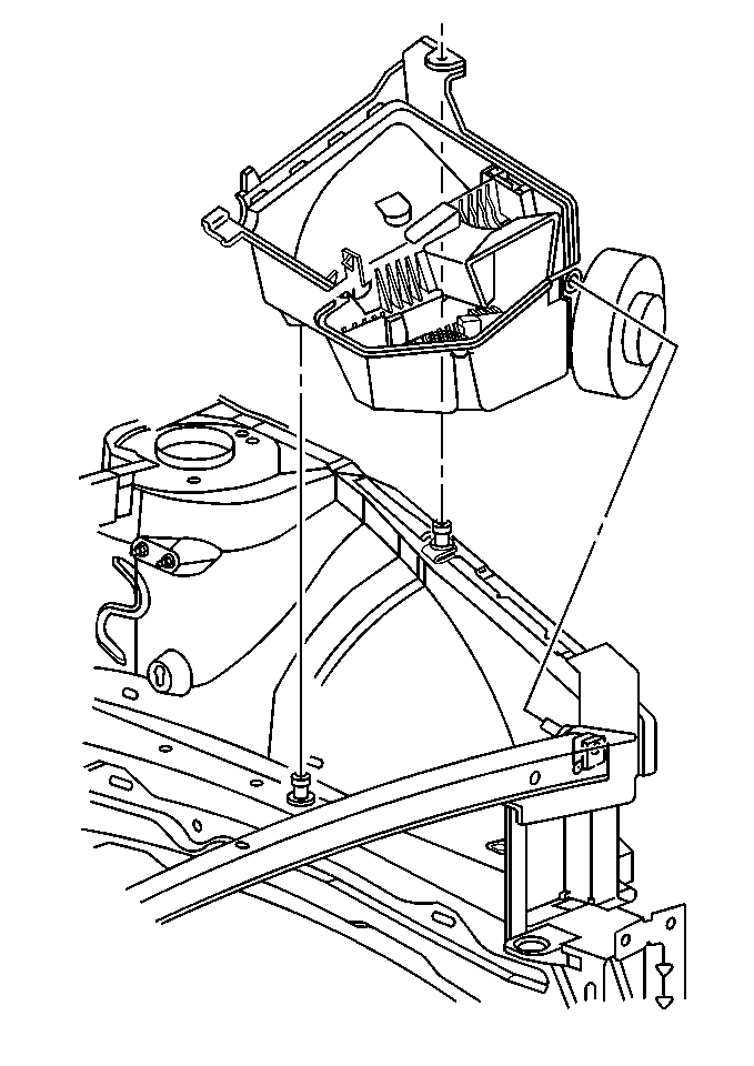
- Pull upwards to remove the lower housing from the locating pins.
- If replacing the upper housing cover, be sure to transfer the air intake duct and MAF/IAT sensor to the replacement housing cover.


Notice:
• Handle the MAF sensor carefully. • Do not drop the MAF sensor in order to prevent damage to the MAF
sensor. • Do not damage the screen located on the air inlet
end of the MAF. • Do not touch the sensing elements. • Do not allow solvents and lubricants to come in contact with the
sensing elements. • Use a small amount of a soap based solution in order to aid in
the installation.
Installation Procedure
- Align the lower housing to the front locating pin.
- Gently push downward to secure the lower housing to the rear locating pins.
- Install the PCM and connector assembly to the lower housing.
- If replacing the upper housing cover, transfer the MAF/IATsensor, intake air ducting, and the clamps to the replacement cover.
- Install the upper housing cover and air intake duct assembly to the throttle body.
- Install the upper housing cover to the lower housing.


Notice:
• Handle the MAF sensor carefully. • Do not drop the MAF sensor in order to prevent damage to the MAF
sensor. • Do not damage the screen located on the air inlet
end of the MAF. • Do not touch the sensing elements. • Do not allow solvents and lubricants to come in contact with the
sensing elements. • Use a small amount of a soap based solution in order to aid in
the installation.
Notice: Use the correct fastener in the correct location. Replacement fasteners must be the correct part number for that application. Fasteners requiring replacement or fasteners requiring the use of thread locking compound or sealant are identified in the service procedure. Do not use paints, lubricants, or corrosion inhibitors on fasteners or fastener joint surfaces unless specified. These coatings affect fastener torque and joint clamping force and may damage the fastener. Use the correct tightening sequence and specifications when installing fasteners in order to avoid damage to parts and systems.
Tighten
Tighten the clamp to 3 N·m (27 lb in).
Tighten
Tighten the clamp to 3 N·m (27 lb in).
Tighten
Tighten the bolts to 4 N·m (35 lb in).
