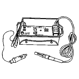
Tools Required
J 39400-A Halogen Leak Detector
Removal Procedure
- Recover the refrigerant from the system. Refer to Refrigerant Recovery and Recharging .
- Disconnect the negative battery cable. Refer to Battery Negative Cable Disconnection and Connection in Engine Electrical.
- Remove the accessory drive belt. Refer to Drive Belt Replacement in Engine Mechanical.
- Raise and support the vehicle. Refer to Lifting and Jacking the Vehicle in General Information.
- Remove the right front tire. Refer to Tire and Wheel Removal and Installation in Tires and Wheels.
- Remove the front air deflector. Refer to Front Air Deflector Replacement in Body Front End.
- Remove the right fascia extension. Refer to Front Bumper Fascia Extension Replacement in Body Front End.
- Disconnect the brake line retaining clips from the engine frame in order to allow the brake lines to move during removal of the A/C compressor.
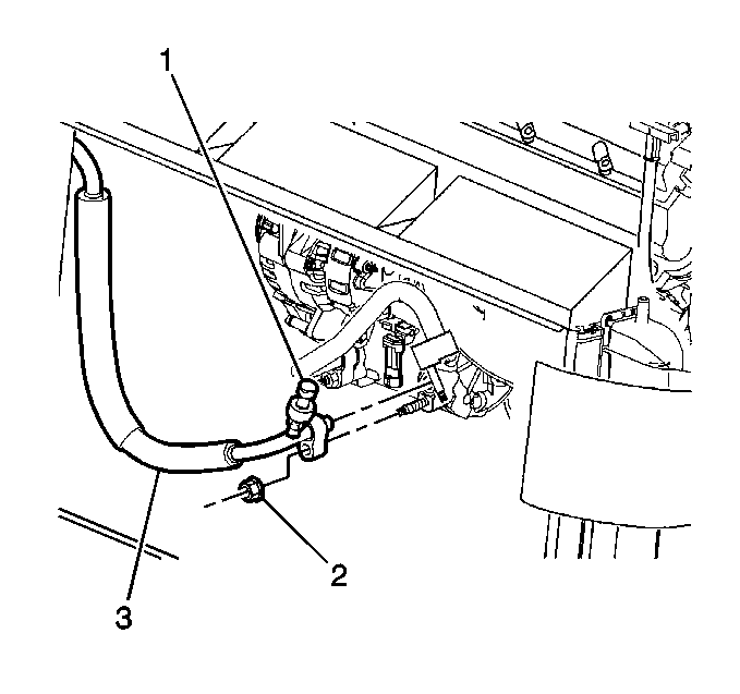
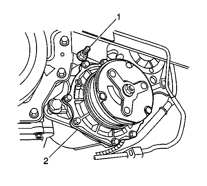
- Remove the nut (2) from the discharge hose (3) and disconnect the discharge hose (3) from the A/C compressor.
- Remove the nut (2) from the suction hose (1) and disconnect the suction hose fitting (1) from the A/C compressor.
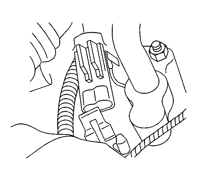
- Disconnect the A/C compressor electrical connector.
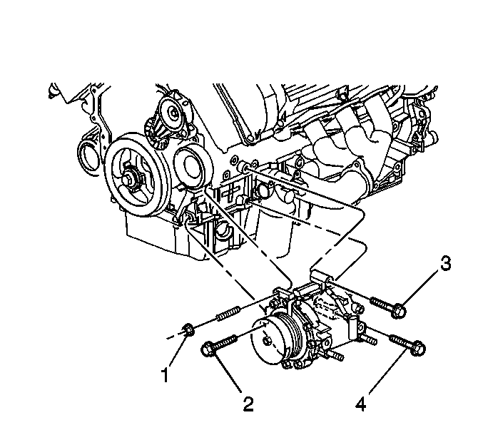
- Remove the A/C compressor mounting fasteners (1, 2, 3, 4).
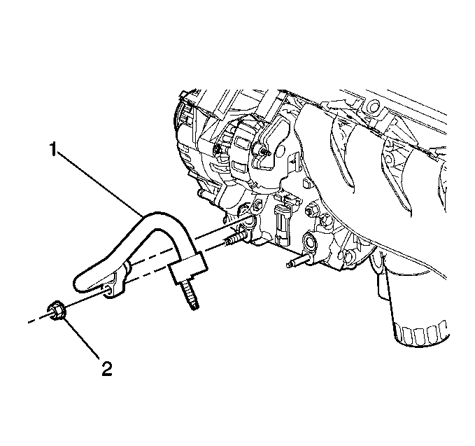
- Remove the A/C compressor (2) mounting stud (1).
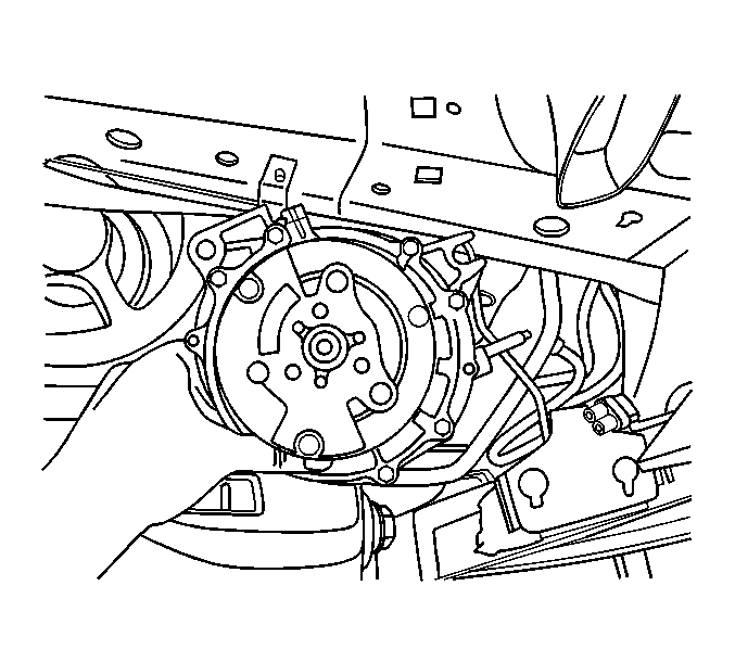
- Rotate the A/C compressor in order to allow the A/C compressor to exit through the wheelhouse opening.
- Remove the A/C compressor from the vehicle.
Important: Seal the A/C compressor suction and discharge ports after the hoses are removed in order to keep contaminants from entering the A/C compressor and oil from draining out of the A/C compressor during removal.
Important: If replacing the compressor, balance the compressor oil. Refer to Compressor Oil Balancing .
Installation Procedure
- Install the A/C compressor through the wheelhouse opening.
- Position the A/C compressor (2) on the mounting surface.
- Install the A/C compressor mounting stud (1) through the appropriate compressor mounting boss.
- Install the A/C compressor mounting fasteners (1, 2, 3, 4) and hand tighten the fasteners.
- Tighten the fasteners in the following sequence:
- Tighten the A/C compressor mounting stud nut (1) to 50 N·m (37 lb ft).
- Tighten the upper rear A/C compressor mounting bolt (3) to 50 N·m (37 lb ft).
- Tighten the front A/C compressor mounting bolt (2) to 50 N·m (37 lb ft).
- Tighten the last lower rear A/C compressor mounting bolt (4) to 25 N·m (18 lb ft).
- Connect the A/C compressor electrical connector.
- Connect the suction hose (1) to the A/C compressor.
- Install the suction hose nut (2) to the A/C compressor.
- Connect the discharge hose (3) to compressor.
- Install the discharge hose nut (2).
- Reconnect the brake line retaining clips to the frame.
- Install the accessory drive belt. Refer to Drive Belt Replacement in Engine Mechanical.
- Install the fascia extension. Refer to Front Bumper Fascia Extension Replacement in Body Front End.
- Install the front air deflector. Refer to Front Air Deflector Replacement in Body Front End.
- Reinstall the right front tire. Refer to Tire and Wheel Removal and Installation in Tires and Wheels.
- Lower the vehicle. Refer to Lifting and Jacking the Vehicle in General Information.
- Connect the negative battery cable. Refer to Battery Negative Cable Disconnection and Connection in Engine Electrical.
- Recharge the A/C system. Refer to Refrigerant Recovery and Recharging .
- Leak test the fittings of the component using J 39400 .
Notice: Use the correct fastener in the correct location. Replacement fasteners must be the correct part number for that application. Fasteners requiring replacement or fasteners requiring the use of thread locking compound or sealant are identified in the service procedure. Do not use paints, lubricants, or corrosion inhibitors on fasteners or fastener joint surfaces unless specified. These coatings affect fastener torque and joint clamping force and may damage the fastener. Use the correct tightening sequence and specifications when installing fasteners in order to avoid damage to parts and systems.
Tighten
Important: Inspect the seal washers for damage before reinstalling the A/C lines.
If any damage is noted during inspection, the suspect seal must be replaced. Flat washer type seals do not require lubrication.
Tighten
Tighten the nut to 16 N·m (12 lb ft).
Tighten
Tighten the nut to 16 N·m (12 lb ft).
