GM Service Manual Online
For 1990-2009 cars only
Figure 1:

Module Power, Ground, Serial Data, and MIL
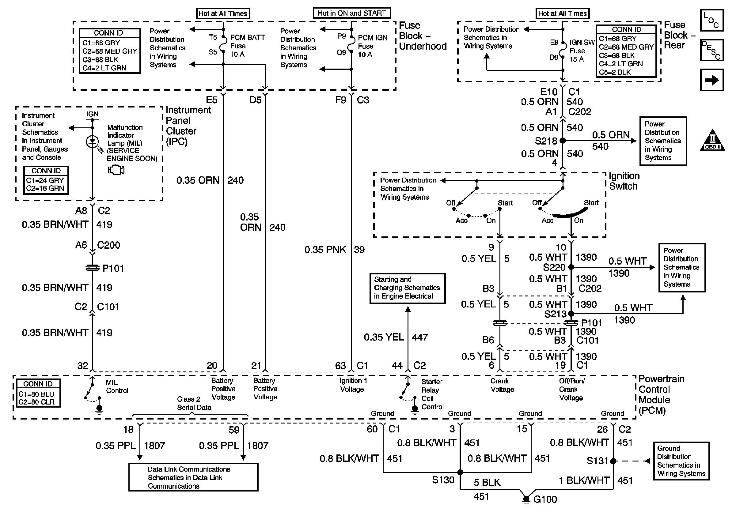

Object Number: 787816  Size: FS
Master Electrical Component List
Powertrain Control Module Description
Engine Data Sensors - 5 Volt and Low Reference
Engine Controls Schematic Icons
Ignition Switch
Ignition Switch
Starter Solenoid Controls
Ignition Switch
Brakes and Engine Indicators
ALDL, PCM BATT, IP Fuses
Ignition Switch
RR BLO, RR DR MDL, HVAC, Stop LP, IGN SW, and TSIG/HAZ Fuses
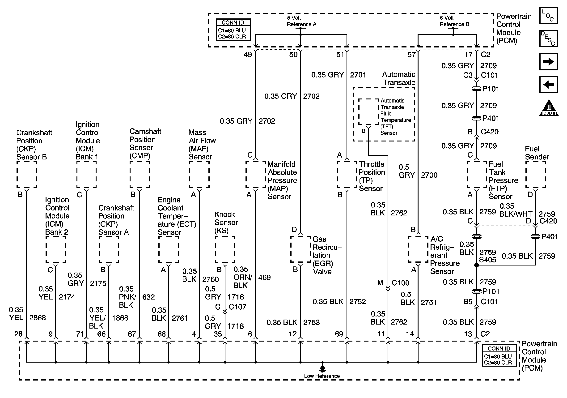
Figure 2:

5 Volt and Low Reference Sensors


Object Number: 787817  Size: FS
Master Electrical Component List
Powertrain Control Module Description
Engine Data Sensors - Pressure and Temperature
Module Power, Ground, Serial Data, MIL
Data Link Communications Schematic Icons
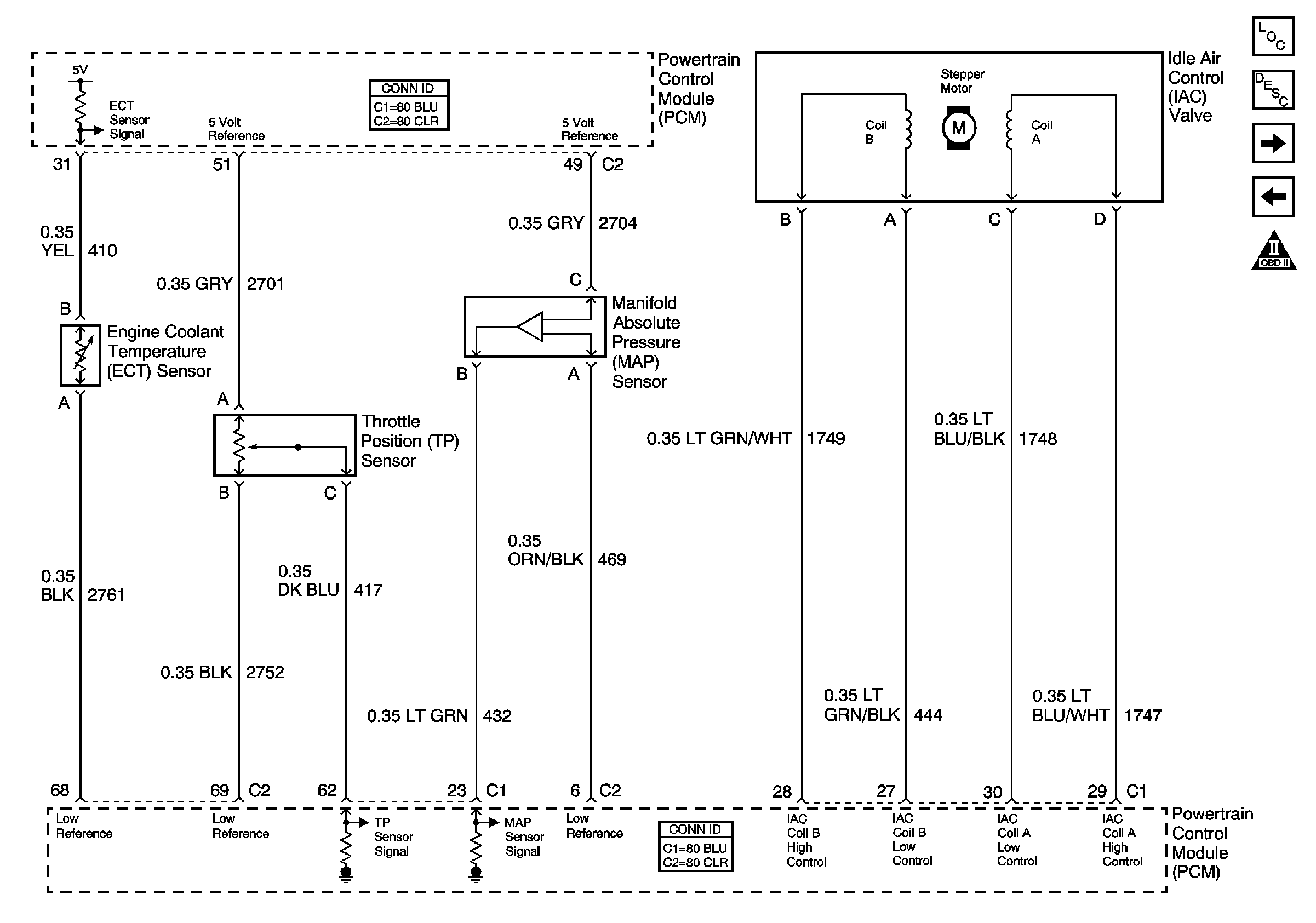
Figure 3:

Pressure and Temperature Sensors


Object Number: 787818  Size: FS
Master Electrical Component List
Powertrain Control Module Description
Engine Data Sensors, MAF, VSS and Extended Brake Travel Switch
Engine Data Sensors - 5 Volt and Low Reference
Data Link Communications Schematic Icons
Figure 4:

MAF,VSS and Extended Brake Travel Switch Sensors
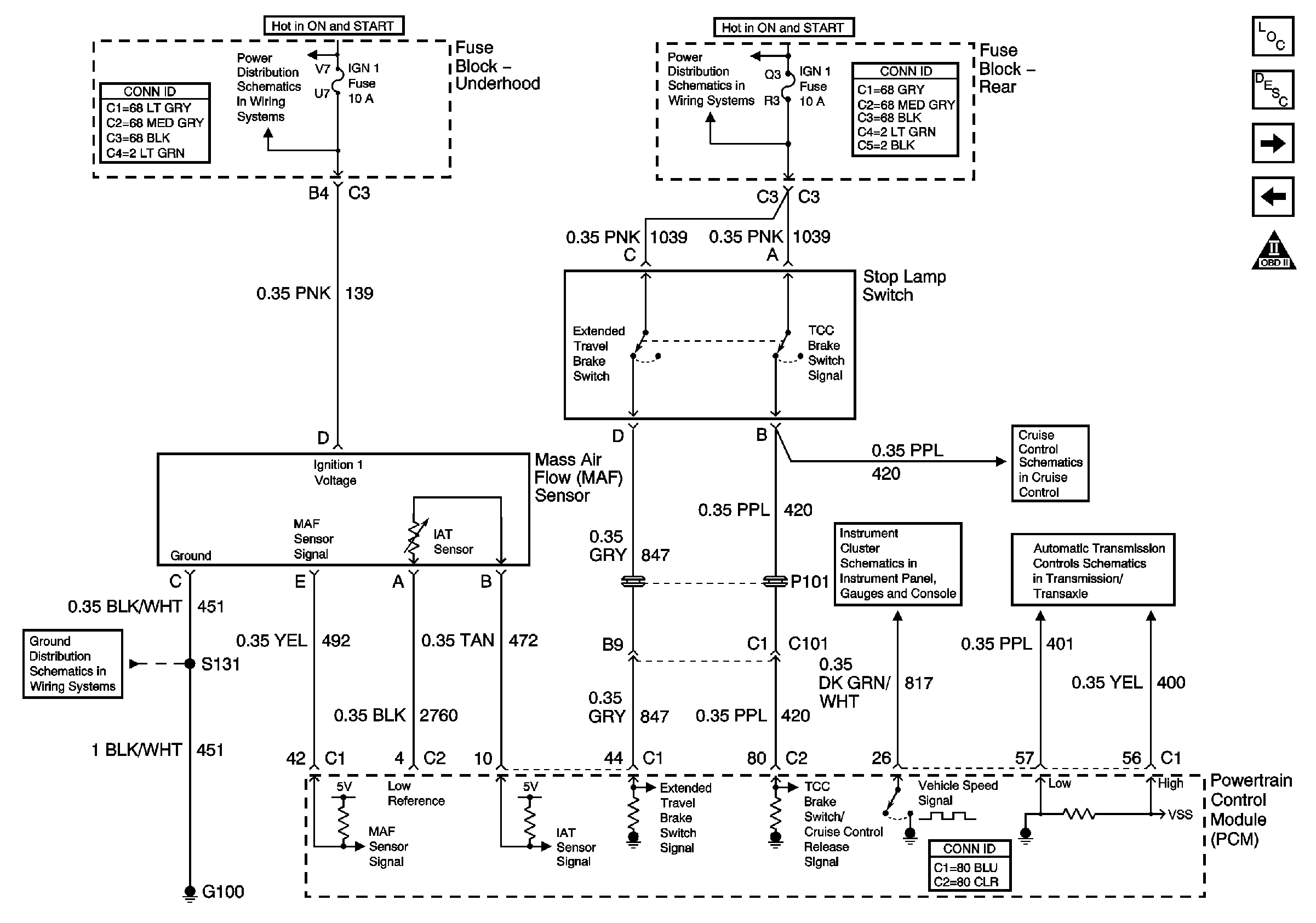

Object Number: 787819  Size: FS
Master Electrical Component List
Powertrain Control Module Description
Engine Data Sensors - O2S and / or HO2S
Engine Data Sensors - Pressure and Temperature
Data Link Communications Schematic Icons
Cruise Control Switches and Module Power and Ground
Automatic Transaxle - IMS Switch and VSS
4.3L Engine Controls Schematics (2 of 20)
G100
Start Circuit Breaker, PCM, IGN and IGN 1 Fuses
SIR, Vent Sol, and IGN 1 Fuses
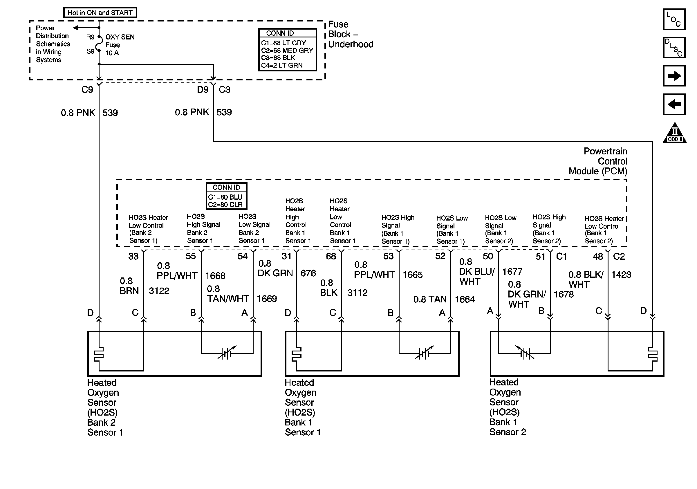
Figure 5:

HO2S Sensors


Object Number: 787820  Size: FS
Master Electrical Component List
Powertrain Control Module Description
Ignition Controls - Ignition System
Engine Data Sensors, MAF, VSS and Extended Brake Travel Switch
Data Link Communications Schematic Icons
Oxy Sen, CR Cont, MDL Coil, Trans Fuses
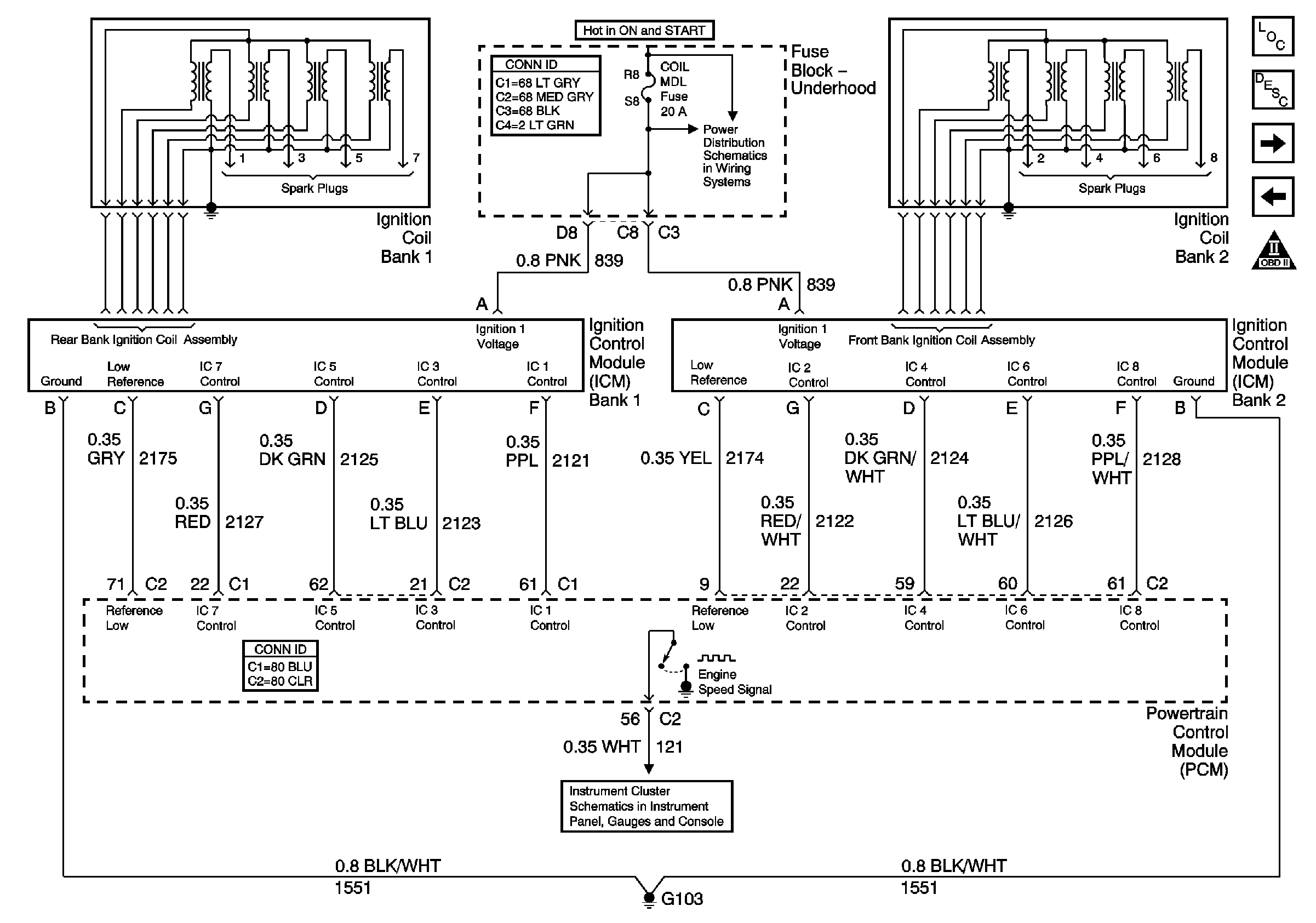
Figure 6:

Ignition Controls and Ignition System


Object Number: 787821  Size: FS
Master Electrical Component List
Powertrain Control Module Description
Ignition Controls - Sensors
Engine Data Sensors - O2S and / or HO2S
Data Link Communications Schematic Icons
Gauges
Oxy Sen, CR Cont, MDL Coil, Trans Fuses
Figure 7:

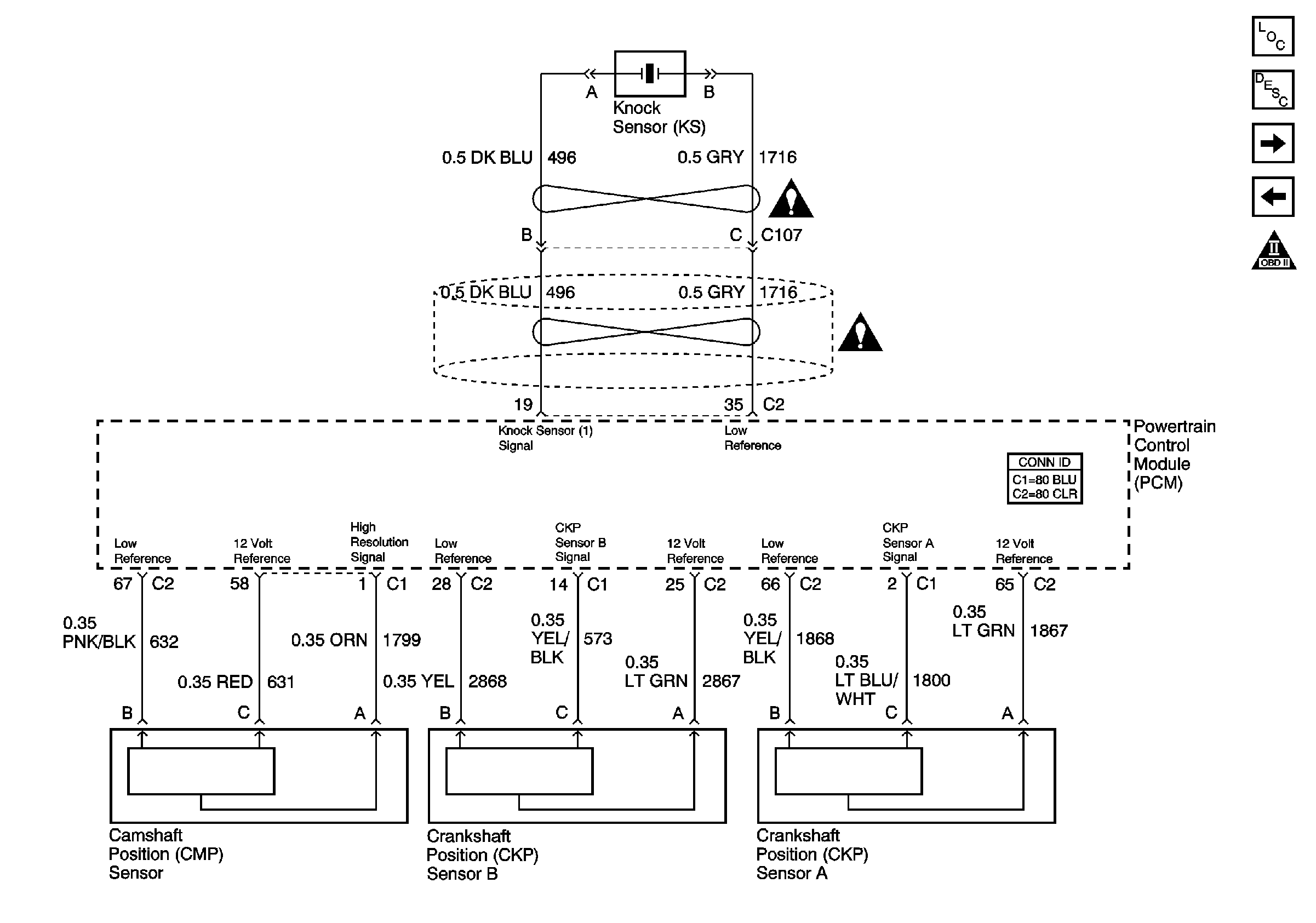
Igniton Controls -- Sensors


Object Number: 787823  Size: FS
Master Electrical Component List
Powertrain Control Module Description
Fuel Controls - Fuel Pump Controls
Ignition Controls - Ignition System
Data Link Communications Schematic Icons
Engine Controls Schematic Icons
Figure 8:

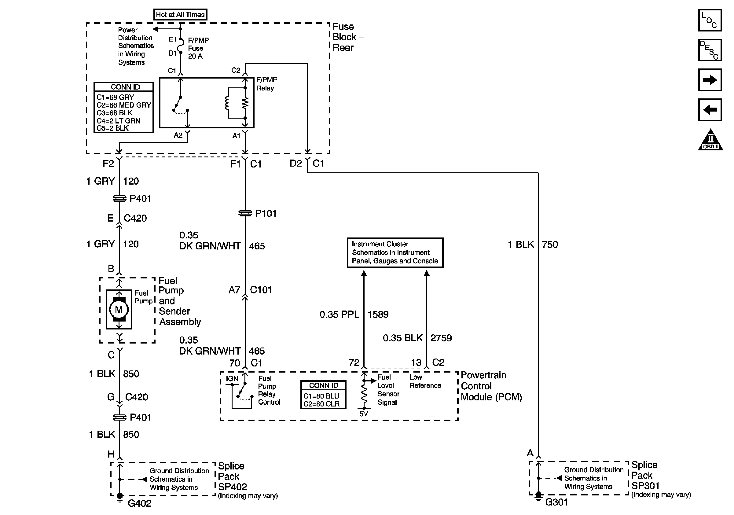
Fuel Controls -- Fuel Pump Controls


Object Number: 787825  Size: FS
Master Electrical Component List
Powertrain Control Module Description
Fuel Controls - Fuel Injectors
Ignition Controls - Sensors
Data Link Communications Schematic Icons
G301
G402 1 of 2
Rear Fuse Block Battery Voltage
Gauges
Figure 9:

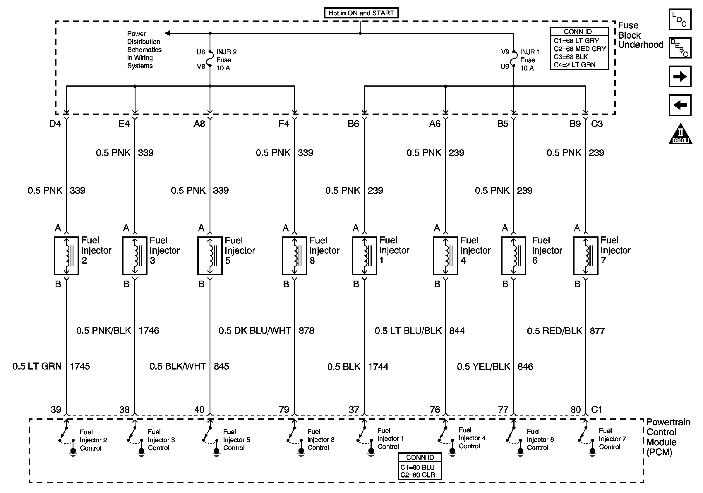
Fuel Controls -- Fuel Injectors


Object Number: 787826  Size: FS
Master Electrical Component List
Powertrain Control Module Description
Fuel Controls - EVAP Controls
Fuel Controls - Fuel Pump Controls
Data Link Communications Schematic Icons
Figure 10:

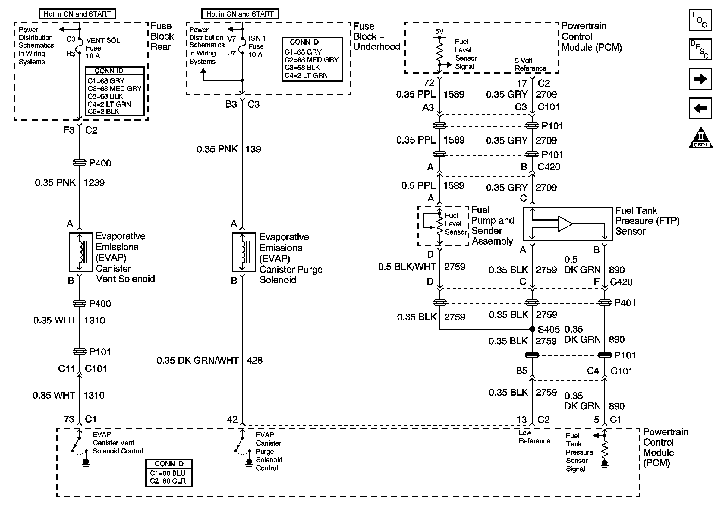
EVAP Controls


Object Number: 787828  Size: FS
Master Electrical Component List
Powertrain Control Module Description
Device Controls
Fuel Controls - Fuel Injectors
Data Link Communications Schematic Icons
SIR, Vent Sol, and IGN 1 Fuses
Figure 11:

Device Controls


Object Number: 787830  Size: FS
Master Electrical Component List
Powertrain Control Module Description
Controlled / Monitored Subsystem References
Fuel Controls - EVAP Controls
Data Link Communications Schematic Icons
G102,G103,G105,G106,G110
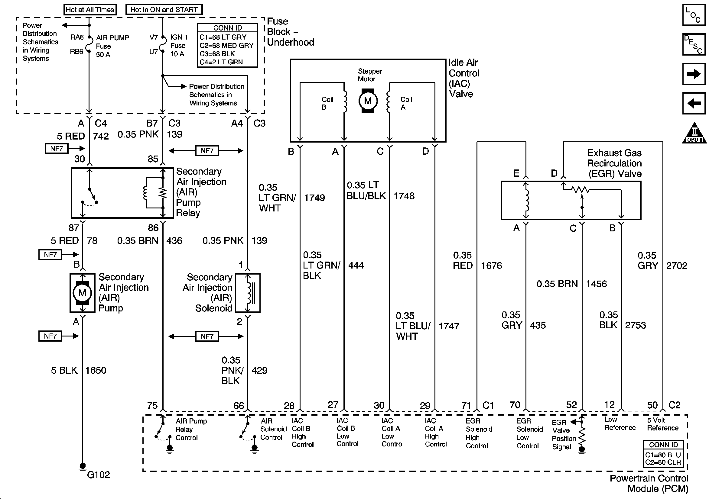
Figure 12:

Controlled/Monitored Subsystem References
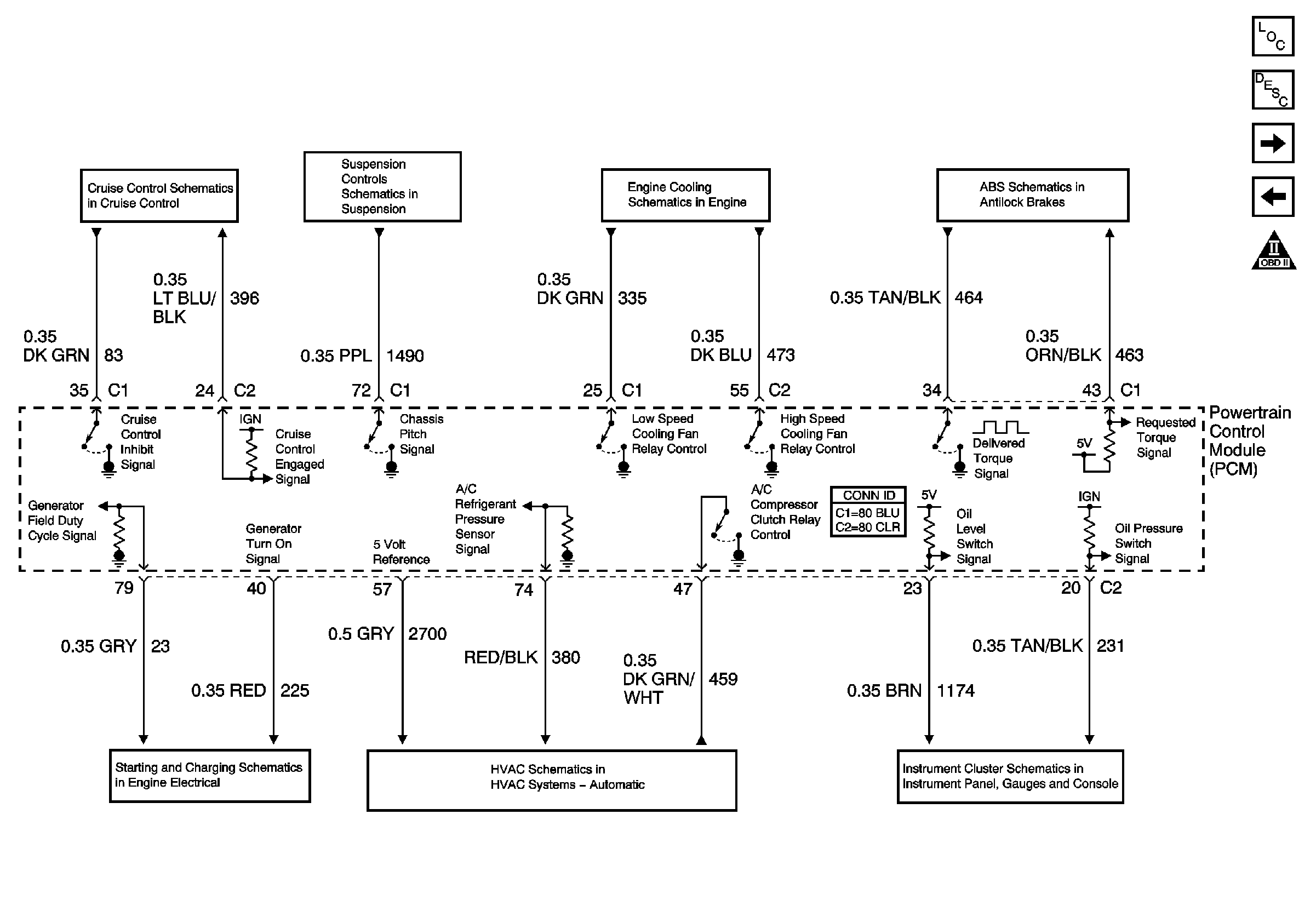

Object Number: 787831  Size: FS
Master Electrical Component List
Powertrain Control Module Description
Transmission Controls - A/T
Device Controls
Data Link Communications Schematic Icons
Brakes and Engine Indicators
HVAC Compressor Control
Generator and Battery
Cruise Control Module PCM Inputs and Vehicle Speed Input
Electronic Suspension Control Module-Pwr and Gnd
Cooling Fans
Suspension Inputs, Class 2, Traction Control, Variable Effort Steering
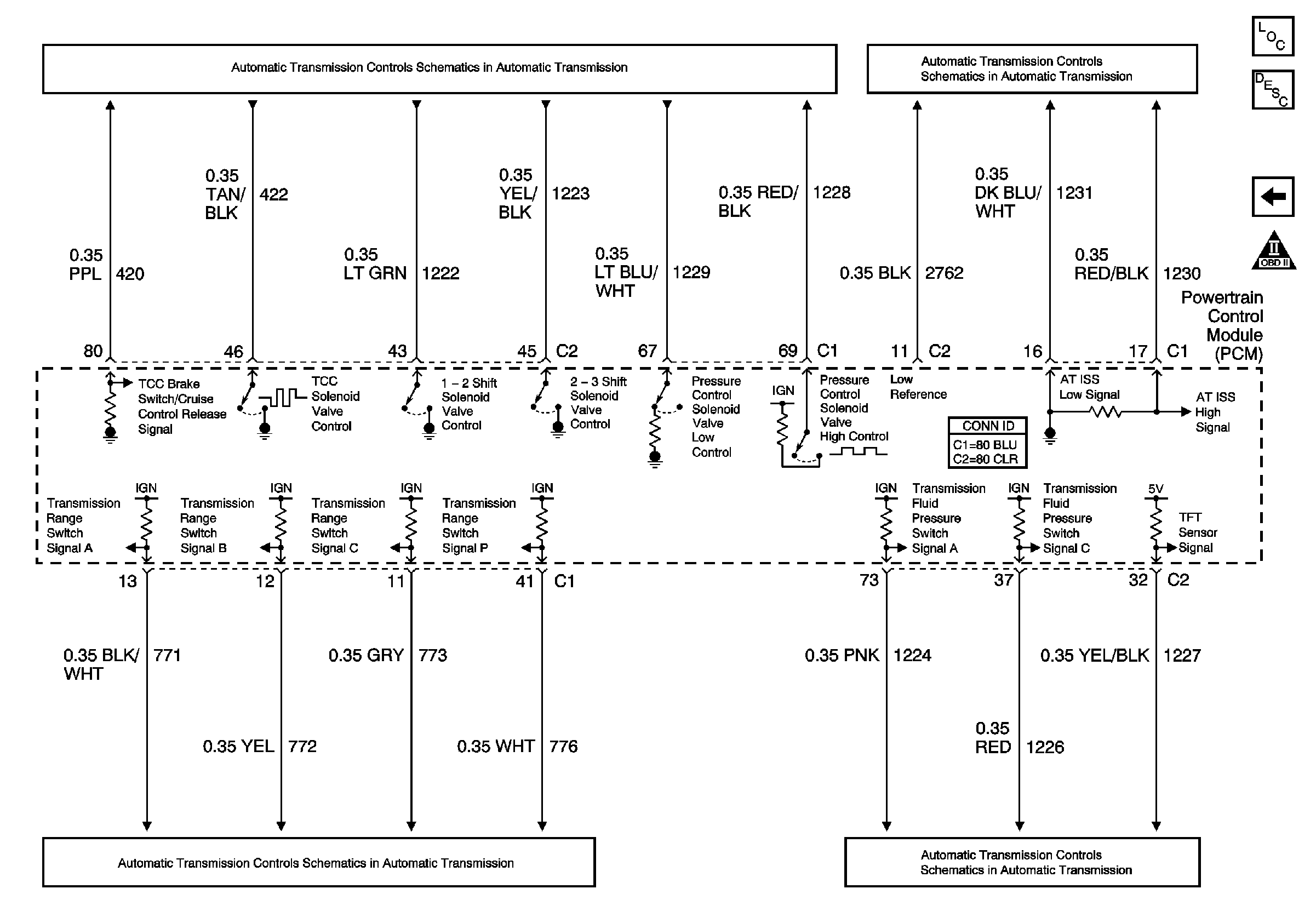
Figure 13:

Transmission Controls -- A/T


Object Number: 787832  Size: FS
Master Electrical Component List
Powertrain Control Module Description
Controlled / Monitored Subsystem References
Data Link Communications Schematic Icons
Automatic Transaxle - Sensors
ABS/TCC Switch and Transaxle Solenoids
Automatic Transaxle - Sensors