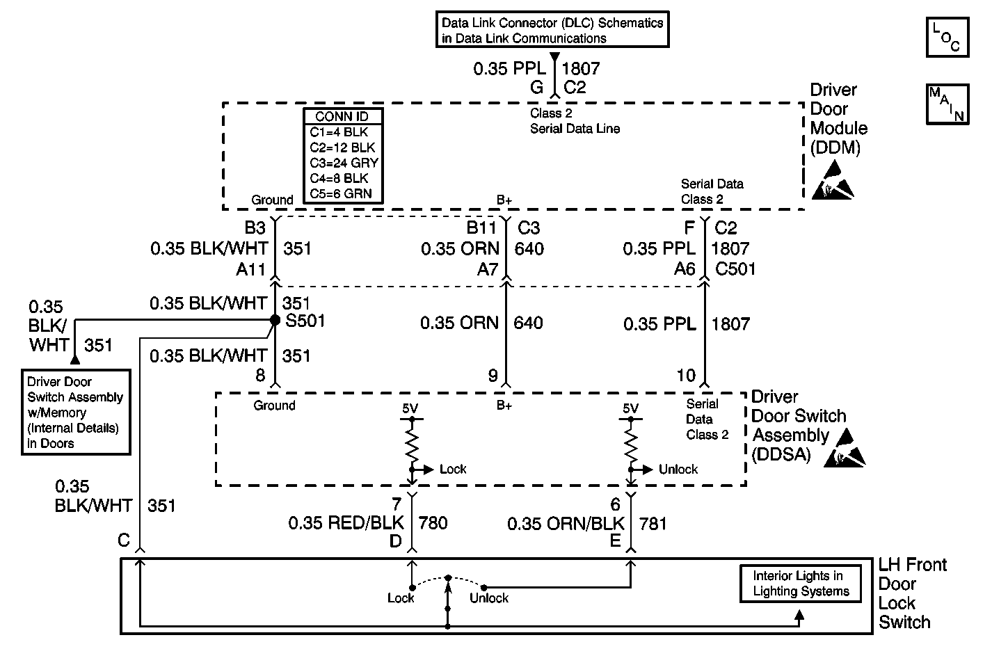
Circuit Description
The Switch that failed and generated this diagnostic trouble code (DTC) is wired to the driver door switch assembly (DDSA). The DDSA processes the inputs from this switch, and then sends a message via the Serial Data Class 2 line to the rear integration module (RIM), which is the master of all lock operations. If the RIM determines that the right conditions are present for unlock activation to take place, it sends its OK back, via the Serial Data Class 2 line, to all of the door modules. Each door module then supplies battery voltage and ground to its associated door lock actuator to Unlock the doors.
Conditions for Running the DTC
The DDSA must be powered and can not have B1327-Battery Voltage Low or B1328-Battery Voltage High set for this DTC to set.
Conditions for Setting the DTC
If the DDSA detects that the circuit is closed for more than 30 continuous seconds in the unlock position, it sets the DTC.
Action Taken When the DTC Sets
The DDSA ignores inputs from this switch and stops sending messages for it.
Conditions for Clearing the MIL/DTC
The DDSA clears this DTC when the switch signal is not received during one of the checks of the circuit.
Diagnostic Aids
A sticking switch can cause this DTC to be set. Refer to Testing for Intermittent Conditions and Poor Connections in Wiring Systems.
Test Description
The numbers below refer to the step numbers on the diagnostic table.
Step | Action | Value(s) | Yes | No |
|---|---|---|---|---|
1 | Did you perform the Door Systems Diagnostic System Check? | -- | Go to Step 2 | |
Does the scan tool display Idle? | -- | Go to Step 3 | Go to Step 4 | |
3 |
Does the Door Lock Switch parameter change state? | -- | Go to Diagnostic Aids | Go to Step 4 |
4 |
Does the scan tool indicate the Idle state? | -- | Go to Step 7 | Go to Step 5 |
5 | Test the driver door lock switch Unlock input circuit for a short to ground. Refer to Circuit Testing and Wiring Repairs in Wiring Systems. Did you find and correct the condition? | -- | Go to Step 10 | Go to Step 6 |
6 | Inspect for poor connections/terminal tension at the driver door switch assembly harness connector. Refer to Testing for Intermittent Conditions and Poor Connections and Connector Repairs in Wiring Systems. Did you find and correct the condition? | -- | Go to Step 10 | Go to Step 8 |
7 | Inspect for poor connections/terminal tension at the driver door lock switch harness connector. Refer to Testing for Intermittent Conditions and Poor Connections and Connector Repairs in Wiring Systems. Did you find and correct the condition? | -- | Go to Step 10 | Go to Step 9 |
8 | Replace the driver door switch assembly . Refer to Front Door Switch Replacement . Did you complete the replacement? | -- | Go to Step 10 | -- |
9 | Replace the driver door lock switch. Refer to Door Lock Switch Replacement . Did you complete the replacement? | -- | Go to Step 10 | -- |
10 |
Does the DTC reset? | -- | Go to Step 2 | System OK |
