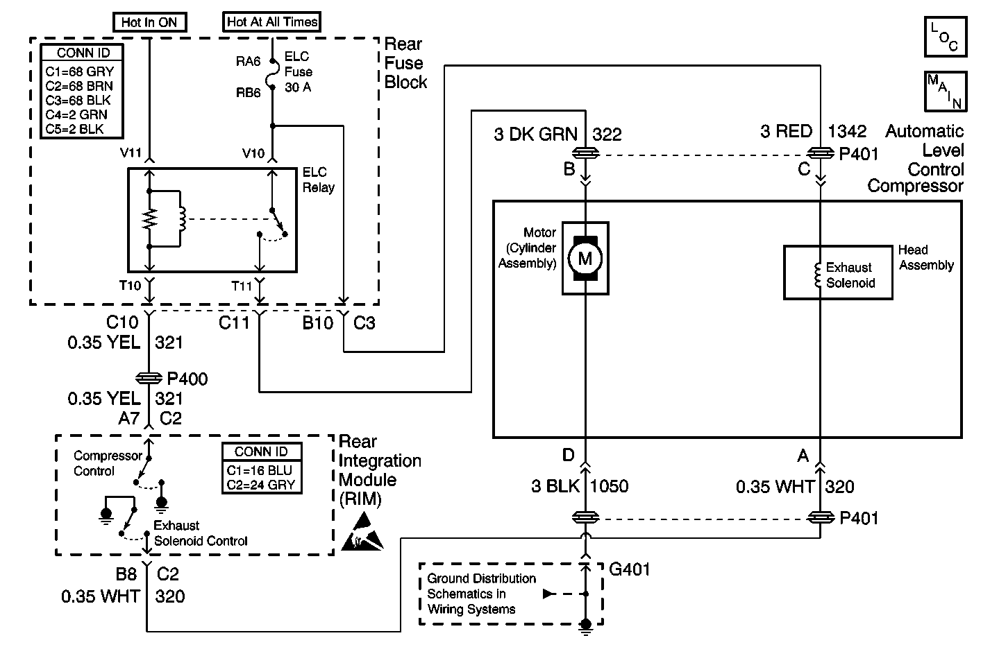
Circuit Description
The automatic level control adjusts the vehicle suspension ride height. The RIM determines the height of the vehicle based on the voltage from the automatic level control sensor. The RIM raises and lowers the rear of the vehicle in order to keep the vehicle level.
Conditions for Running the DTC
| • | The RIM is powered up. |
| • | DTC B1327 is not set. |
Conditions for Setting the DTC
The exhaust valve solenoid output is found to be open or shorted to ground for 10 seconds.
Action Taken When the DTC Sets
The automatic level control will be inoperative.
Conditions for Clearing the MIL/DTC
When the RIM does not detect a failure during the self test.
Diagnostic Aids
| • | Inspect for the addition of any aftermarket components. |
| • | Inspect all wiring carefully for chaff's and proper routing. Refer to Testing for Electrical Intermittents and Testing for Intermittent Conditions and Poor Connections in Wiring Systems. |
Test Description
The numbers below refer to the step numbers on the diagnostic table.
-
Listen for an audible click when the exhaust solenoid operates. Command both the ON and OFF states. Repeat the commands as necessary.
-
Tests if ground is constantly being applied to the solenoid.
Step | Action | Value(s) | Yes | No |
|---|---|---|---|---|
1 | Did you perform the Automatic Level Control Diagnostic System Check? | -- | ||
Does the exhaust solenoid valve turn ON and OFF with each command? | -- | Go to Diagnostic Aids | ||
3 |
Does the test lamp illuminate? | -- | ||
4 |
Does the test lamp turn ON and OFF with each command? | -- | ||
Does the test lamp remain illuminated with each command? | -- | |||
6 | Test the control circuit of the exhaust solenoid valve for a short to voltage or an open. Refer to Connector Repairs and Wiring Repairs in Wiring Systems. Did you find and correct the condition? | -- | ||
7 | Test the control circuit of the exhaust solenoid valve for a short to ground. Refer to Testing for Intermittent Conditions and Poor Connections and Wiring Repairs in Wiring Systems. Did you find and correct the condition? | -- | ||
8 | Inspect for poor connections at the exhaust solenoid. Refer to Testing for Intermittent Conditions and Poor Connections and Connector Repairs in Wiring Systems. Did you find and correct the condition? | -- | ||
9 | Inspect for poor connections at the harness connector for the RIM. Refer to Testing for Intermittent Conditions and Poor Connections and Connector Repairs in Wiring Systems. Did you find and correct the condition? | -- | ||
10 | Repair the coil side feed circuit of the exhaust solenoid valve. Refer to Wiring Repairs in Wiring Systems. Did you complete the repair? | -- | -- | |
11 | Replace the compressor head assembly. Refer to Automatic Level Control Air Compressor Head Replacement . Did you complete the replacement? | -- | -- | |
12 | Replace the RIM. Refer to Rear Integration Body Control Module Replacement in Body Control Systems. Did you complete the replacement? | -- | -- | |
13 |
Does the DTC reset? | -- | System OK |
