Front Floor Console Replacement DTS, w/o UV8
Removal Procedure
Caution: Refer to SIR Caution in the Preface section.
- Disable the SIR. Refer to Disabling the SIR System in SIR.
- Set the parking brake.
- Remove the left console trim panel. Refer to Front Floor Console Side Trim Panel Replacement - Left Side .
- Remove the right console trim panel. Refer to Front Floor Console Side Trim Panel Replacement - Right Side .
- Remove the console center trim plate. Refer to Front Floor Console Trim Plate Replacement .
- Remove the IP center compartment. Refer to Instrument Panel Compartment Replacement .
- Remove the left knee bolster. Refer to Driver Knee Bolster Replacement .
- Remove the right knee bolster. Refer to Passenger Knee Bolster Replacement .
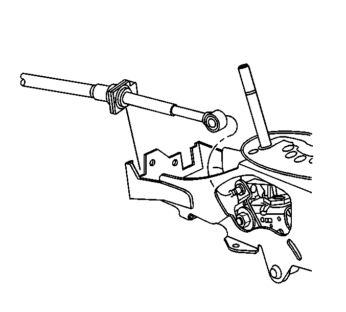
- Disconnect the transaxle range selector cable terminal from the shift lever pin.
- Pull the lock release and remove the transaxle shift cable from the console.
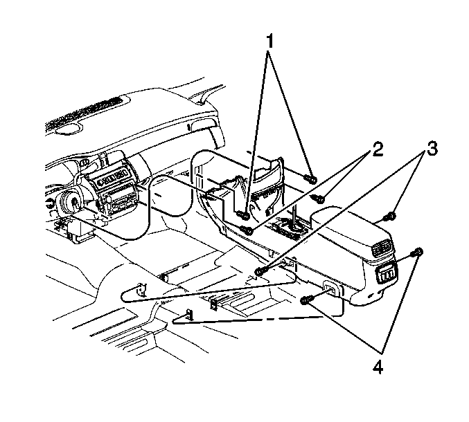
- Remove the 4 console fasteners (1, 2) to the IP.
- Adjust the front seats rearward.
- Remove the 2 front console to floor fasteners (3).
- Adjust the front seats forward.
- Remove the 2 rear console to floor fasteners (4).
- Move the console rearward, in order to access the electrical connectors.
- Disconnect the center console electrical connectors.
- Remove the center console.
Installation Procedure
- Install the center console to the vehicle.
- Connect the center console electrical connectors.
- Align the locating pins on the center console to the IP.
- Install the 2 upper console to IP fasteners (1).
- Install the 2 lower console to IP fasteners (2).
- Adjust the front seats to the forward position.
- Install the 2 rear console to floor fasteners (4).
- Adjust the front seats to the rear position.
- Install the 2 front console to floor fasteners (3).
- Install the IP center compartment. Refer to Instrument Panel Compartment Replacement
- Slide the transaxle range selector cable fully into the console until it snaps into place.
- Connect the transaxle range selector cable terminal to the shift lever pin.
- Install the console center trim plate. Refer to Front Floor Console Trim Plate Replacement .
- Install the right knee bolster. Refer to Passenger Knee Bolster Replacement .
- Install the left knee bolster. Refer to Driver Knee Bolster Replacement .
- Install both the left and the right console trim panels. Refer to Front Floor Console Side Trim Panel Replacement - Left Side and Front Floor Console Side Trim Panel Replacement - Right Side .
- Enable the SIR system. Refer to Enabling the SIR System in SIR.

Notice: Use the correct fastener in the correct location. Replacement fasteners must be the correct part number for that application. Fasteners requiring replacement or fasteners requiring the use of thread locking compound or sealant are identified in the service procedure. Do not use paints, lubricants, or corrosion inhibitors on fasteners or fastener joint surfaces unless specified. These coatings affect fastener torque and joint clamping force and may damage the fastener. Use the correct tightening sequence and specifications when installing fasteners in order to avoid damage to parts and systems.
Tighten
Tighten the fasteners (1) to 9 N·m (80 lb in).
Tighten
Tighten the fasteners (2) to 9 N·m (80 lb in).
Tighten
Tighten the fasteners (4) to 9 N·m (80 lb in).
Tighten
Tighten the fasteners (3) to 9 N·m (80 lb in).

Front Floor Console Replacement DTS, UV8
Removal Procedure
Caution: When you are performing service on or near the SIR components or the SIR wiring, you must disable the SIR system. Refer to Disabling the SIR System. Failure to follow the correct procedure could cause air bag deployment, personal injury, or unnecessary SIR system repairs.
- Disable air bag system. Refer to Disabling the SIR System in SIR.
- Set the parking brake.
- Remove the left console trim panel. Refer to Front Floor Console Side Trim Panel Replacement - Left Side .
- Remove the right console trim panel. Refer to Front Floor Console Side Trim Panel Replacement - Right Side .
- Remove the console center trim plate. Refer to Front Floor Console Trim Plate Replacement .
- Remove the IP center compartment. Refer to Instrument Panel Compartment Replacement .
- Remove the left knee bolster. Refer to Driver Knee Bolster Replacement .
- Remove the right knee bolster. Refer to Passenger Knee Bolster Replacement .
- Disconnect the transaxle range selector cable terminal from the shift lever pin.
- Pull the lock release and remove the transaxle shift cable from the console.
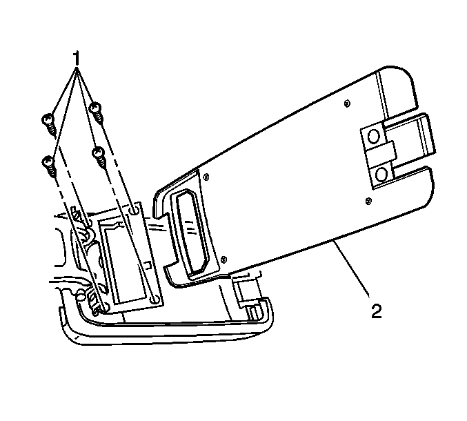
- Remove the console tray (2). Refer to Front Floor Console Storage Tray Replacement
- Remove the console tray insert from the console tray (2). Refer to Console Tray Insert Replacement .
- Remove the interface card from the console tray insert.
- Disconnect the interface card electrical connector.
- Remove the rear HVAC control. Refer to Control Assembly Replacement - Rear in HVAC-Automatic.
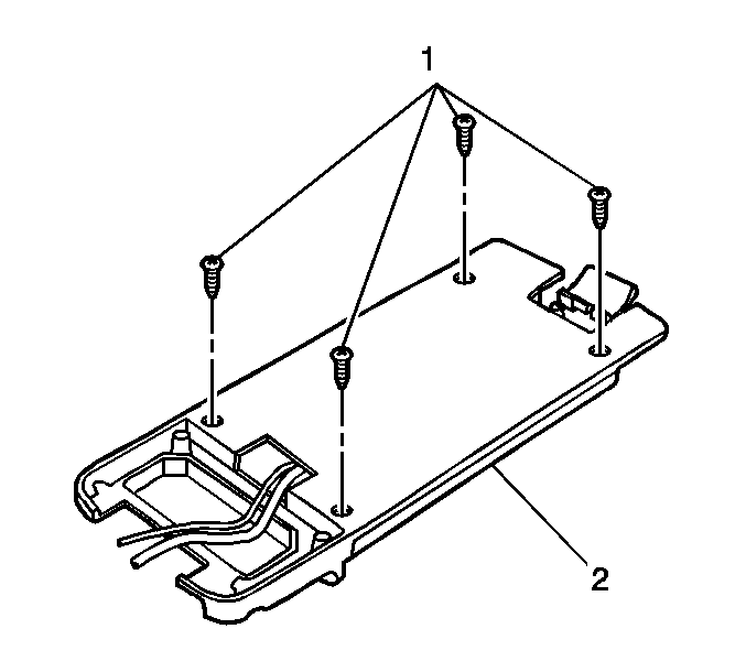
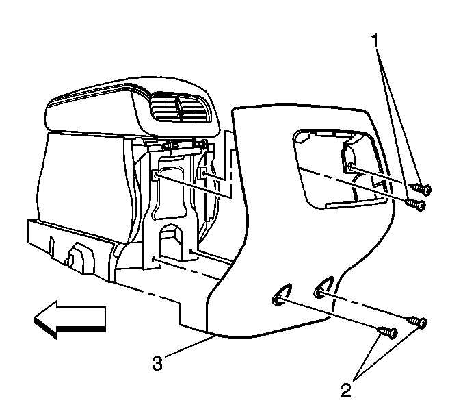
- Remove the center console endcap fasteners (1, 2).
- Remove the center console endcap (3).
- Disconnect the coaxial cable from the coil cord.
- Remove the cellular phone wiring from the center console.
- Remove the four console fasteners (1, 2) to the IP.
- Adjust the front seats rearward.
- Remove the two front console to floor fasteners (3).
- Adjust the front seats forward.
- Remove the two rear console to floor fasteners (4).
- Move the console rearward, in order to access the center console electrical connectors.
- Disconnect the center console electrical connectors.
- Remove the center console.


Installation Procedure
- Install the front floor console to the vehicle.
- Route the cellular phone wiring through the center console to the tray insert area.
- Connect the coaxial cable to the coil cord.
- Connect the interface card electrical connector.
- Install the center console endcap (3).
- Install the center console endcap fasteners (1, 2).
- Tighten the fasteners (1,2) fully driven, seated, but not stripped.
- Install the auxiliary HVAC control. Refer to Control Assembly Replacement - Rear in HVAC-Automatic.
- Install the interface card to the console tray insert.
- Install the console tray insert to the console tray (2). Refer to Console Tray Insert Replacement .
- Connect the center console electrical connectors.
- Align the locating pins on the floor console to the IP.
- Install the two upper console to IP fasteners (1).
- Install the two lower console to IP fasteners (2).
- Adjust the front seats to the forward position.
- Install the two rear console to floor fasteners (4).
- Adjust the front seats to the rear position.
- Install the two front console to floor fasteners (3).
- Slide the transaxle range selector cable fully into the console until it snaps into place.
- Connect the transaxle range selector cable terminal to the shift lever pin.
- Install the IP center storage compartment. Refer to Instrument Panel Compartment Replacement .
- Install the console center trim plate. Refer to Front Floor Console Trim Plate Replacement .
- Install the right knee bolster. Refer to Passenger Knee Bolster Replacement .
- Install the left knee bolster. Refer to Driver Knee Bolster Replacement .
- Install both the left and the right console trim plates. Refer to Front Floor Console Side Trim Panel Replacement - Left Side and Front Floor Console Side Trim Panel Replacement - Right Side .
- Enable the SIR system. Refer to Enabling the SIR System in SIR.


Notice: Use the correct fastener in the correct location. Replacement fasteners must be the correct part number for that application. Fasteners requiring replacement or fasteners requiring the use of thread locking compound or sealant are identified in the service procedure. Do not use paints, lubricants, or corrosion inhibitors on fasteners or fastener joint surfaces unless specified. These coatings affect fastener torque and joint clamping force and may damage the fastener. Use the correct tightening sequence and specifications when installing fasteners in order to avoid damage to parts and systems.
Tighten
Tighten the fasteners to 1.6 N·m (14 lb in).

Tighten
Tighten the fasteners (1) to 9 N·m (80 lb in).
Tighten
Tighten the fasteners (2) to 9 N·m (80 lb in).
Tighten
Tighten the fasteners (4) to 9 N·m (80 lb in).
Tighten
Tighten the fasteners (3) to 9N·m (80 lb in).

