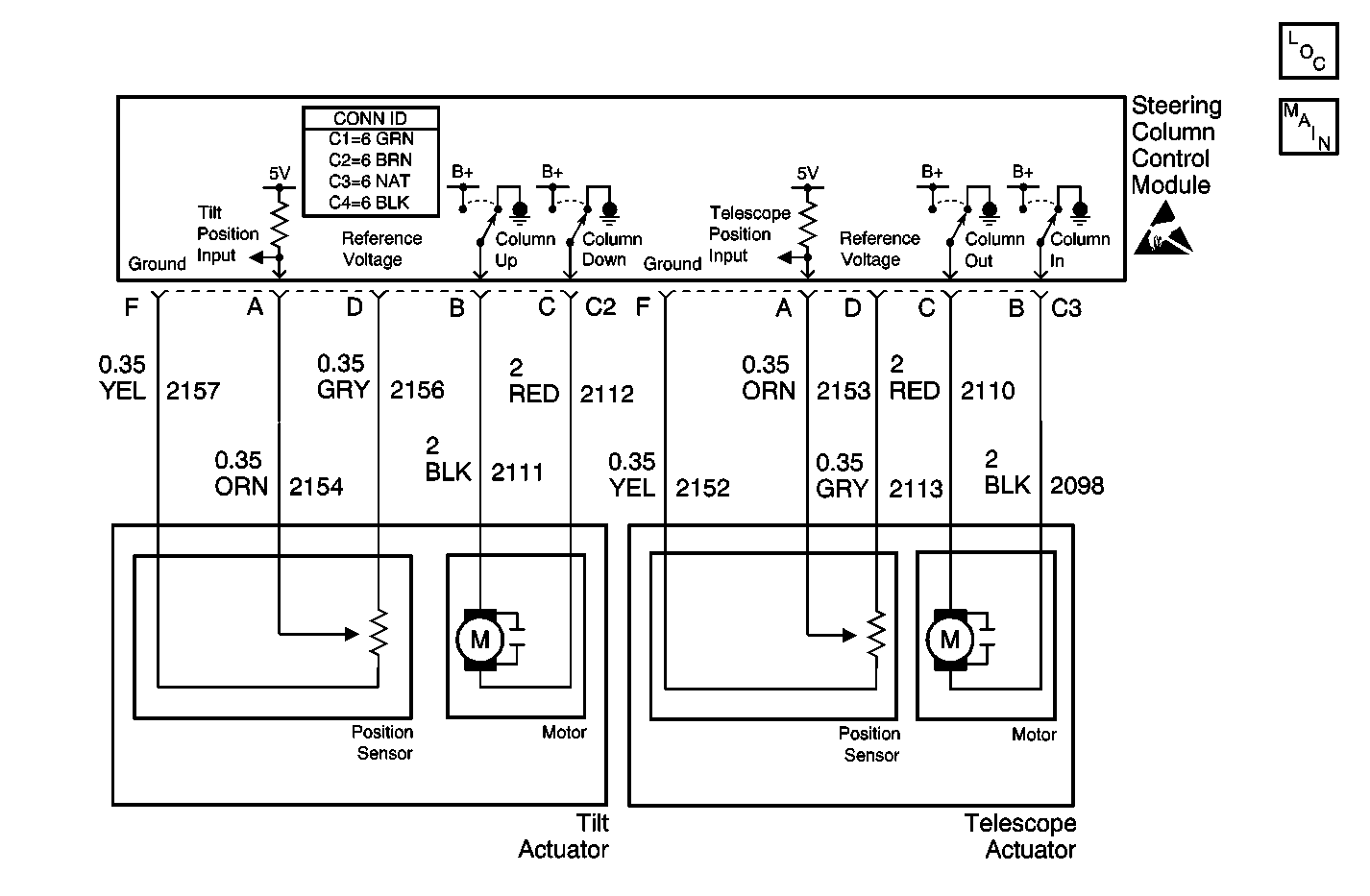
Circuit Description
The tilt/telescoping steering column module (SCCM) determines the position of the steering column based on inputs received from sensors that are built into the tilt actuator and the telescoping actuator. The SCCM supplies a 5 volt reference signal and a ground to these sensors and monitors the column position via a tilt position input circuit and a telescope position input circuit.
Conditions for Running the DTC
The self diagnostics test runs once every 30 seconds if there is no current code B1327 Battery Voltage Low set.
Conditions for Setting the DTC
During normal operation, the steering column position sensor inputs are compared to values that are stored in the memory of the SCCM. The current code will be set by the SCCM when the sensor inputs and the limits stored in its memory differ for a time period of 2 seconds. At that time, the SCCM will determine the circuit to be shorted.
Action Taken When the DTC Sets
When a sensor code is set as current, the SCCM will not allow the affected motor to work during memory recall and/or easy exit operations. However, the motor will still operate for manual switch positioning.
Conditions for Clearing the DTC
| • | The SCCM no longer detects the failure. |
| • | Use the scan tool in order to clear the code. |
| • | Use the On-Board Diagnostics to clear the code. |
Diagnostic Aids
| • | Check the steering column for abnormal looseness. |
| • | It is important to reprogram the SCCM following the replacement of any SCCM electrical component. |
Step | Action | Value(s) | Yes | No |
|---|---|---|---|---|
1 | Did you perform the Tilt/Telescoping Steering Column Diagnostic System Check? | -- | Go to Step 2 | Go to Tilt/Telescoping Steering Column Diagnostic System Check |
2 |
Does the scan tool indicate that the Data parameter is greater than the specified value? | 0.12 Volts | Go to Diagnostic Aids | Go to Step 3 |
3 |
Does the scan tool indicate that the Data parameter is greater than the specified value? | 4.8 Volts | Go to Step 4 | Go to Step 6 |
4 | Inspect for poor connections at the harness connector of the tilt actuator. Refer to Testing for Intermittent Conditions and Poor Connections and Connector Repairs in Wiring Systems. Did you find and correct the condition? | -- | Go to Step 7 | Go to Step 5 |
5 |
Important: Perform the set up procedure for the tilt/telescoping steering column control module. Replace the tilt actuator. Refer to Tilt Motor Assembly - Disassemble - Off Vehicle . Did you complete the replacement? | -- | Go to Step 7 | -- |
6 |
Important: Perform the set up procedure for the tilt/telescoping steering column control module. Replace the tilt/telescoping steering column control module. Refer to Steering Column Control Module Replacement . Did you complete the replacement? | -- | Go to Step 7 | -- |
7 |
Does the DTC reset? | -- | Go to Step 2 | System OK |
