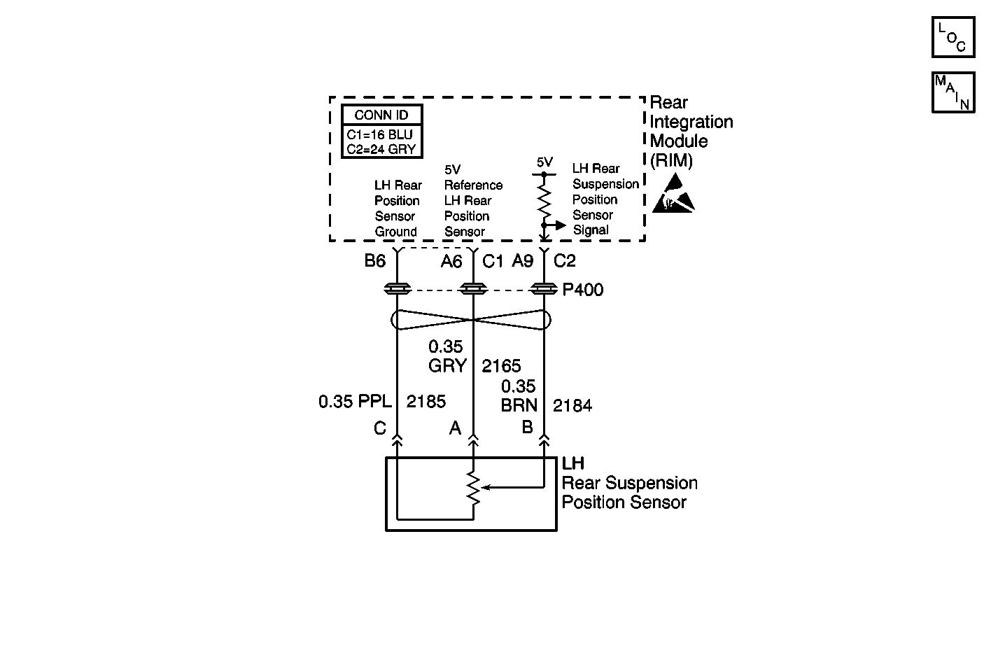
Circuit Description
The automatic level control sensor is a potentiometer. The RIM determines the height of the rear of the vehicle based on the voltage from the automatic level control sensor. The RIM raises or lowers the rear of the vehicle in order to keep the vehicle level.
Conditions for Running the DTC
The RIM is powered up and DTC B1327 is not set.
Conditions for Setting the DTC
| • | The automatic level control signal voltage is less that 0.3 V or greater than 4.7 V. |
| • | The above conditions are present for greater than 10 seconds. |
Action Taken When the DTC Sets
The automatic level control suspension will be inoperative.
Conditions for Clearing the MIL/DTC
The RIM does not detect a voltage above or below the predetermined value during the diagnostic self test.
Diagnostic Aids
Refer to Testing for Intermittent Conditions and Poor Connections
in Wiring Systems.
Test Description
The numbers below refer to the step numbers on the diagnostic table.
-
Tests for the proper operation of the circuit in the high range. If the fuse in the jumper opens when you perform the test, the signal circuit is shorted to ground.
-
Tests for a short to voltage in the 5-volt reference circuit.
Step | Action | Value(s) | Yes | No |
|---|---|---|---|---|
1 | Did you perform the Automatic Level Control Diagnostic System Check? | -- | ||
2 |
Does the scan tool indicate the voltage is within the specified range? | 0.5-4.75 V | Go to Diagnostic Aids | |
3 |
Does the voltage measure near the specified value? | 5 V | ||
Does the scan tool indicate that the suspension position sensor voltage is greater than the specified value? | 4.75 V | |||
Does the voltage measure less than the specified value? | 4.75 V | |||
6 |
Does the resistance measure less than the specified value? | 5 ohms | ||
7 | Test the 5-volt reference circuit of the suspension position sensor for a short to ground, high resistance, or an open. Refer to Circuit Testing and Wiring Repairs in Wiring Systems. Did you find and correct the condition? | -- | ||
8 | Test the 5-volt signal circuit of the suspension position sensor for a short to ground, high resistance, or an open. Refer to Circuit Testing and Wiring Repairs in Wiring Systems. Did you find and correct the condition? | -- | ||
9 | Test the signal circuit of the suspension position sensor for a short to voltage. Refer to Circuit Testing and Wiring Repairs in Wiring Systems. Did you find and correct the condition? | -- | ||
10 |
Did you find and correct the condition? | -- | ||
11 | Inspect for poor connections at the harness connector of the suspension position sensor. Refer to Testing for Intermittent Conditions and Poor Connections and Connector Repairs in Wiring Systems. Did you find and correct the condition? | -- | ||
12 | Inspect for poor connections at the harness connector of the RIM. Refer to Testing for Intermittent Conditions and Poor Connections and Connector Repairs in Wiring Systems. Did you find and correct the condition? | -- | ||
13 | Replace the suspension position sensor. Refer to Automatic Level Control Sensor Replacement . Did you complete the replacement? | -- | -- | |
14 | Replace the RIM. Refer to Rear Integration Body Control Module Replacement in Body Control Systems. Did you complete the replacement? | -- | -- | |
15 |
Does the DTC reset? | -- | System OK |
