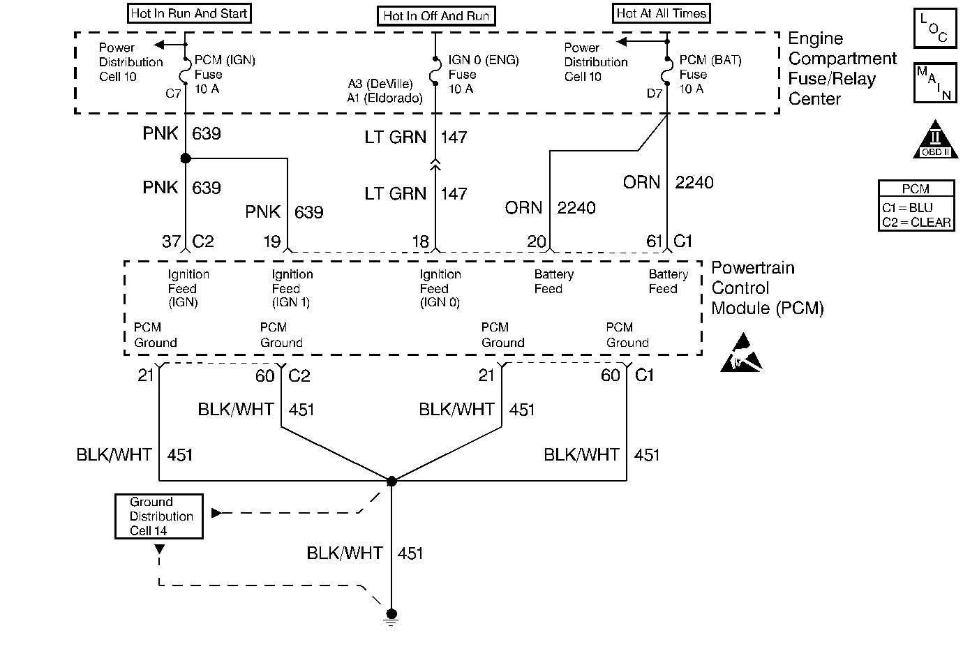
Circuit Description
The PCM is powered with 5 power feeds. Two of these feeds are from the battery, the other three are from the ignition switch and are called Ignition 1, Ignition Supplement and Ignition 0. Ignition 1 and Ignition Supplement are powered any time the key is in the CRANK , RUN or ACC positions. Ignition 0 is powered in ALL key positions except LOCK and CRANK. This diagnostic test is used to monitor the Ignition Supplement voltage received at PCM connector C2 terminal 37. The PCM monitors this voltage and if it drops too low for 1 second, DTC P1633 will set.
Conditions for Running the DTC
| • | Engine running |
| • | Ignition 1 voltage, PCM connector C1 terminal 19, at least 5.5 volts. |
Conditions for Setting the DTC
Ignition Supplement voltage, PCM connector C2 terminal 37, voltage low for 1 second.
Action Taken When the DTC Sets
| • | The Malfunction Indicator Lamp (MIL) will not illuminate. |
| • | The PCM will command a message to be displayed. |
| • | The PCM may record operating conditions at the time the diagnostic fails. This information will be stored in the Failure Records. |
Conditions for Clearing the Message/DTC
| • | The PCM will turn the message OFF after one run and pass of the diagnostic test. |
| • | A History DTC will clear after forty consecutive warm-up cycles with no failures of any non-emission related diagnostic test. |
| • | A Last Test Failed (current) DTC will clear when the diagnostic runs and does not fail. |
| • | Use a scan tool to clear DTCs. |
| • | Interrupting PCM battery voltage may or may not clear DTCs. This practice is not recommended. Refer to Powertrain Control Module Description . |
Diagnostic Aids
If this DTC is intermittent check terminal contact at the PCM and the condition of the CKT 639 splice for an intermittent open condition.
If the Ignition 0 to the PCM is lost the vehicle will still run but some outputs may not function, if the Ignition 1 voltage is lost or goes below 5.5 volts the vehicle will not run but DTC P1634 should set.
Step | Action | Value(s) | Yes | No |
|---|---|---|---|---|
1 | Did you perform the Powertrain On-Board Diagnostic (OBD) System Check? | -- | Go to Step 2 | |
2 | Is DTC P1634 also set? | -- | Go to DTC P1631 Theft Deterrent Start Enable Signal Not Correct | Go to Step 3 |
3 |
Are the two voltages within each other by the value specified? | 1.5 volts | Go to Step 4 | Go to Step 5 |
4 |
Did this DTC fail this ignition cycle? | -- | Go to Step 6 | Fault not present. Refer to Diagnostic Aids |
5 | Repair the open in CKT 639 between PCM connector C2 terminal 37 and the splice or poor terminal contact at PCM connector C2 terminal 37. Is the repair complete? | -- | Go to Powertrain Control Module Diagnosis for Verify Repair | -- |
6 |
Was terminal contact repaired? | -- | Go to Powertrain Control Module Diagnosis for Verify Repair | Go to Step 7 |
7 | Replace the PCM. Refer to Powertrain Control Module Replacement/Programming . Is the replacement complete? | -- | Go to Powertrain Control Module Diagnosis for Verify Repair | -- |
