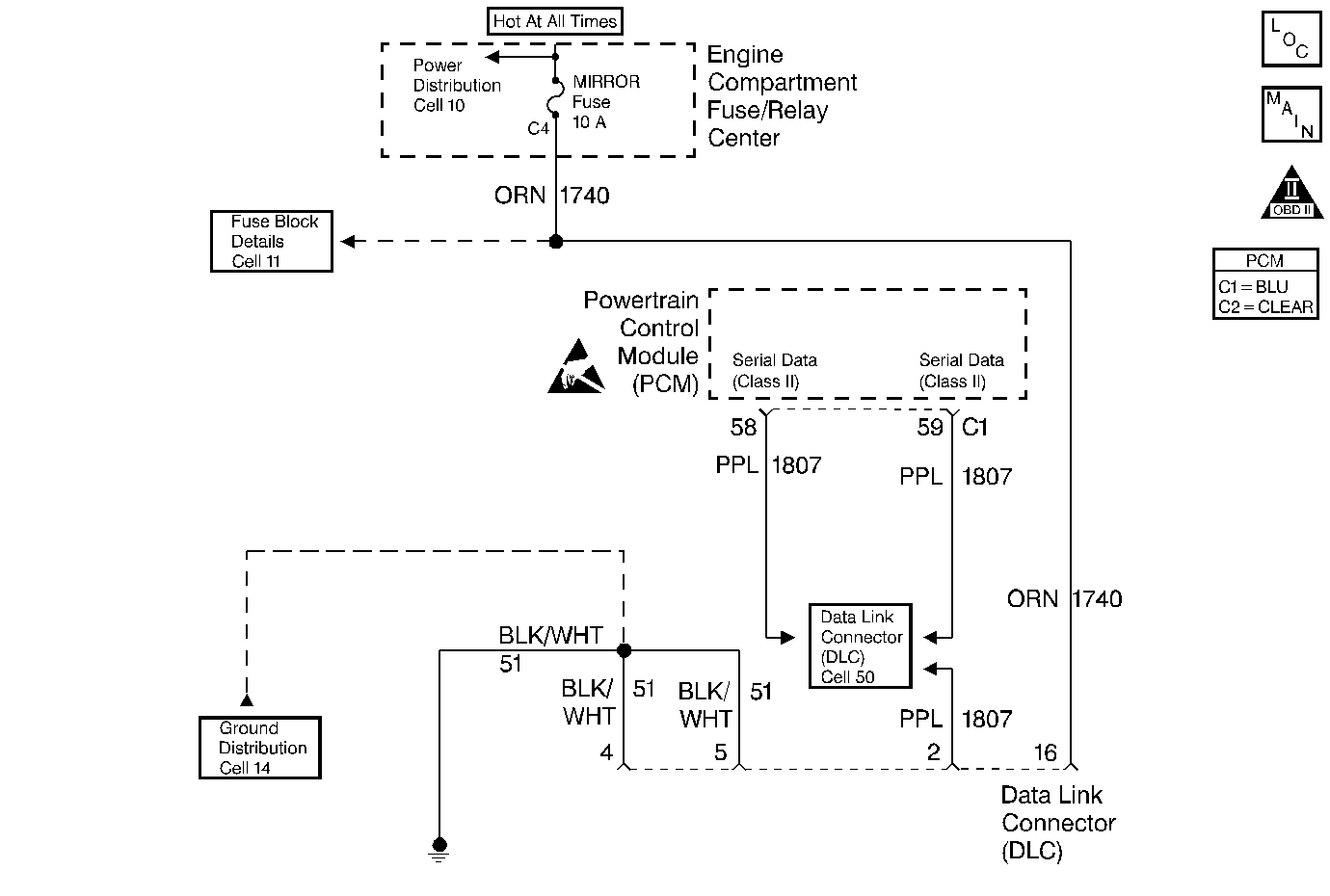
Circuit Description
The Data Link Connector check is used to identify the cause of an inoperative scan tool. Possible faults include scan tool non-power up and lack of communication between the scan tool and the PCM. The DLC supplies power to the scan tool through CKT 1740 to terminal 16. The ground to the scan tool is supplied through CKT 51 to terminal 5. The serial data (communication) is supplied to the scan tool through CKT 1807 to terminal 2.
Diagnostic Aids
Perform the Powertrain OBD System Check before using this diagnostic procedure to help prevent miss-diagnosis.
Test Description
Number(s) below refer to the step number(s) on the Diagnostic Table.
-
Checking the voltage and ground supply to the scan tool.
-
Checking if the fault is power or ground circuit related.
-
Terminal 4 of the DLC connector is the ground circuit for scan tool data communications and terminal 5 is the power ground circuit for the scan tool.
-
If communication is present between the scan tool and PCM then the fault is not present or was poor terminal contact at the DLC connector.
-
Checking if the fault is vehicle or scan tool related.
-
On analog dash vehicles press and hold the OFF and passenger warmer temperature buttons simultaneously. On digital dash vehicles press and hold the OFF and warmer temperature buttons simultaneously.
If On-Boards do not function there may be a short to ground on CKT 1807 anywhere on the circuit or one of the control modules connected to Class 2 may be faulty. Refer to Body Electrical to diagnose the serial data line.
-
Due to the multiple connections to serial data, if no DTCs are present the fault should be between the DLC and the splice.
Step | Action | Value(s) | Yes | No |
|---|---|---|---|---|
1 | Did you perform the Powertrain OBD System Check? | -- | ||
2 | Perform the PCM Power and Ground Check and the Powertrain Ground Check and return to this step. Was a repair made in either check? | -- | ||
Is the voltage read on both terminals the same or higher than the value shown? | 10.0 Volts | |||
Measure voltage to ground on DLC terminal 16. Is the voltage read the same or higher than the value shown? | 10.0 Volts | |||
Repair the open in the ground circuit that had low or no voltage. Refer to Test Descriptions. Is the repair complete? | -- | -- | ||
6 |
Is the repair complete? | -- | -- | |
Turn the ignition ON. Does the scan tool display data? | -- | |||
Connect the scan tool to another vehicle. Does the scan tool now display data? | -- | |||
Does the vehicle enter On-Board Diagnostics? | -- | Go to Body Electrical for diagnosis | ||
10 | Using On-Board Diagnostic display, check for serial data DTCs for all the modules. Are any serial data DTCs set? | -- | Go to DTCs that are set. | |
Check for an open CKT 1807 between the DLC connector terminal 2 and the CKT 1807 DLC/ PZM/ IPC/ Mem seat splice. Was an open found and repaired? | -- | |||
12 |
Does the scan tool now display data? | -- | ||
13 | Replace the scan tool. Is the replacement complete? | -- | -- | |
14 | Replace the PCM. Refer to Powertrain Control Module Replacement/Programming . Is the replacement complete? | -- | -- |
