FRONT SUSPENSION SQUEAKS REPAIR PROCEDURE OUTLINED

MODELS AFFECTED: 1985 AND 1986 DE VILLES AND FLEETWOODS
This bulletin supersedes 87-26 which should be destroyed. Please note the change in Warranty Information at the end of this bulletin.
Some 1985 and 1986 De Villes and Fleetwoods may exhibit a squeak during slow speed turns, usually during initial drive after the vehicle has been parked for several hours. This condition may be caused by upper strut mount to bearing interference. To repair this condition, use the following parts and repair procedure:
PARTS
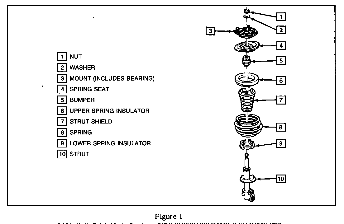
Description P/N ----------- --- Mount (W/Touring Suspension)* 17985937 Mount (W/O Touring Suspension)* 17985660 Front Suspension Bumper 25529882 Spring Seat 25528290 Strut Shield 25530150 Nut 25526968 Washer 14013513 * includes Bearing
REPAIR PROCEDURE
Removing Strut From Car:
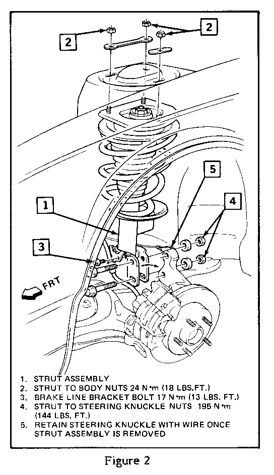
1. Remove three nuts attaching top of each strut assembly to body, refer to Figure 2. If front suspension was previously aligned and caster was adjusted (i.e., all body holes are slotted) scribe position of strut washers on strut tower using a sharp tool before loosening nuts. Upon reassembly, align marks with washers and front end alignment will not be necessary.
2. Raise car on a suspension contact hoist.
3. Install jack stands under frame and lower vehicle slightly so weight of vehicle rests on jack stands and not on control arms. Do not allow control arms to hang free.
4. Remove tire and wheel assemblies.
5. Remove brake line bracket bolt from strut assemblies.
6. Use a sharp tool and scribe knuckle with an outline of strut flange. Upon reassembly, align marks and front end alignment will not be necessary.
NOTICE: Care must be taken to avoid over extending drive axle inner tri-pot joints. Over extension could result in separation of internal components which could go un- detected and result in faiture of the joint.
7. Remove strut to knuckle bolts.
IMPORTANT: Knuckle must be retained at top to avoid over extending tri-pot joint. Refer to Figure 2.
8.Remove strut assembly from vehicle.
Installing New Mount, Bumper, Spring Seat, and Strut Shield:
Tools Required:
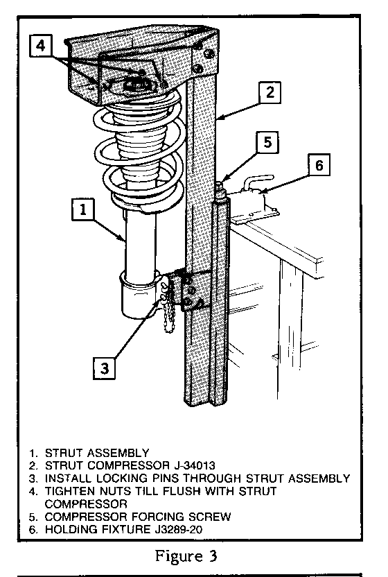
J-3289-20 Holding Fixture J-34013 Spring Compressor J-34013-20 Clamp J-34013-38 Guiding Rod
NOTICE: Care should be taken to avoid chipping or cracking the spring coating when handling the front suspension coil spring. Damage to the coating could result in spring failure.
1. Install strut compressor tool J-34013 in Holding Fixture J-3289-20 as shown in Figure 3.
2. Install strut assembly in toof J-34013 as shown in Figure 3.
3. Turn compressor forcing screw until spring compresses slightly.
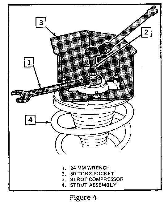
4. Hold damper shaft from turning (50 Torx) and remove nut on top of strut assembly (24mm) as shown in Figure 4.
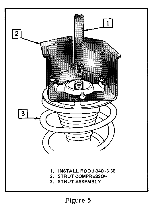
5. Install rod 9-34013-39 to help guide damper shaft out of assembly, see Figure 5.
6. Loosen compressor forcing screw while guiding damper shaft out of assembly. Continue loosening nut until strut dampner and spring can be removed.
7. Remove upper locking pin and remove mount, spring seat, bumper, and strut shield.
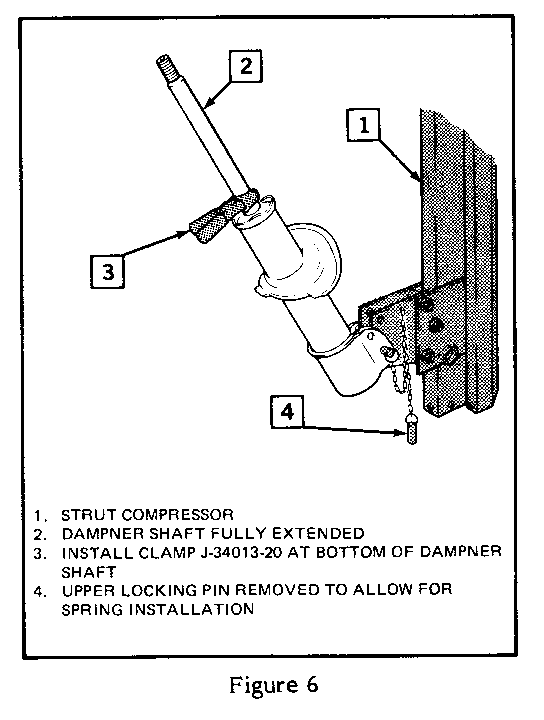
8. Install clamp J-34013-20 on damper shaft as shown in Figure 6.
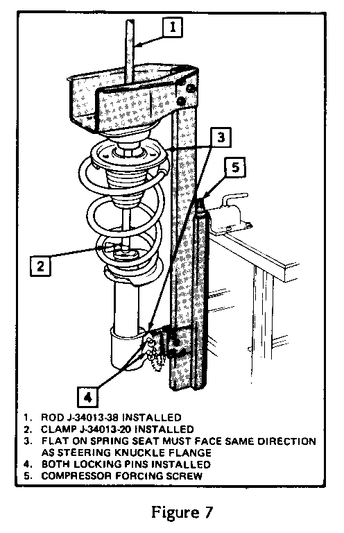
9. Install spring over strut in correct position. Install strut shield, bumper, spring seat, mount and move assembly upright in Strut Compressor Install upper locking pin, Figure 7.
IMPORTANT: Flat on upper spring seat must face outward 90 degrees from centerline of vehicle Figure 7. When mounted in Strut Compressor spring seat faces the same direction as steering knuckle mounting flange.
1O. Install rod J-34013-38 into strut assembly to guide dampner shaft for reassembly of strut.
11. Start turning compressor forcing screw on tool J-34013 clockwise while guiding Rod J-34013-38 to center damper shaft in the assembly.
12. Continue to turn compressor forcing screw on tool until damper shaft threads are visible through top of strut assembly.
13. Install new washer and nut, using a 24mm crows foot line wrench and #50 Torx. Tighten to 60 N.m (44 ft. lbs.).
14. Remove clamp J-34013-20 from damper shaft.
15. Remove two locking pins at bottom of tool.
16. Remove strut assembly from compressor.
Installing Strut On Car
1. Install strut and three nuts attaching strut to body, refer to Figure 2. If scribe marks were made in Step 1 of "Removing Strut From Car" align strut washers with scribe marks. Tighten nuts to 24 N.m (18 f t. lbs.).
2. Install knuckle to strut bolts, refer to Figure 2. Carefully align strut with scribe marks made in step 6 of "Removing Strut From Car." Tighten bolts to 1985 N.m (144 ft. lbs.).
3. Install brake line bracket to strut bolt. Tighten to 17 N.m (13 ft. lbs.).
4. Install wheel and tire assembly. Tighten to 140 N.m (100 lbs. ft.).
5. Raise vehicle and remove jack stands.
6. Lower vehicle.
WARRANTY
For warranty purposes, use Labor Operation E3927 (replace both side strut mounts) at 1.4 hours.
General Motors bulletins are intended for use by professional technicians, not a "do-it-yourselfer". They are written to inform those technicians of conditions that may occur on some vehicles, or to provide information that could assist in the proper service of a vehicle. Properly trained technicians have the equipment, tools, safety instructions and know-how to do a job properly and safely. If a condition is described, do not assume that the bulletin applies to your vehicle, or that your vehicle will have that condition. See a General Motors dealer servicing your brand of General Motors vehicle for information on whether your vehicle may benefit from the information.
