Caution: Refer to Brake Fluid Irritant Caution in the Preface section.
Notice: Refer to Brake Fluid Effects on Paint and Electrical Components Notice in the Preface section.
Notice: Hydraulic brake systems use two distinct and incompatible fluids. Power steering fluid is used in the hydraulic brake booster system. Brake fluid is used in the master cylinder and brake pipes. Use extreme care when selecting brake system fluids, or seal damage can result. Refer to General Information to select the correct fluid.
Removal Procedure
- Disconnect the battery negative cable.
- Place the vehicle on a level surface.
- Block the front wheels.
- Apply the parking brake.
- Disconnect the power steering inlet hose. Refer to Power Steering Return Hose Replacement .
- Disconnect the power steering pressure hose. Refer to Power Steering Pressure Pipe/Hose Replacement .
- Disconnect the power steering gear to booster hose. Refer to Power Steering Pressure Pipe/Hose Replacement .
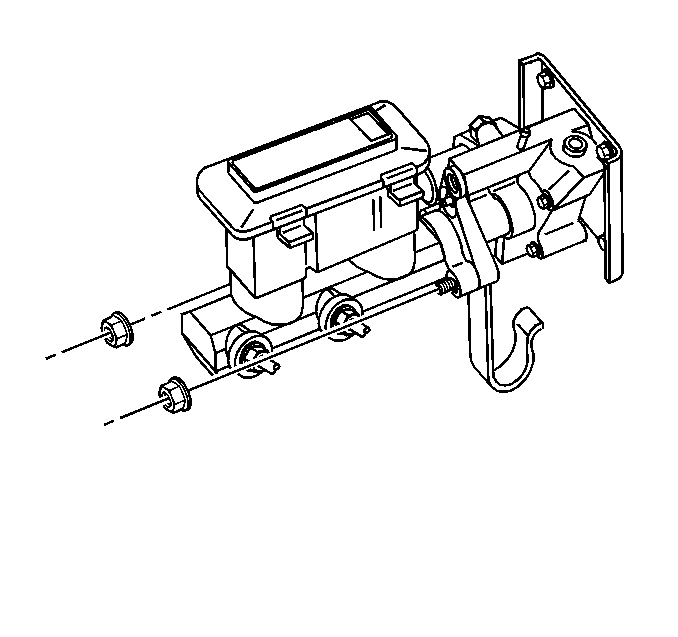
- Remove the master cylinder. Refer to Master Cylinder Replacement .
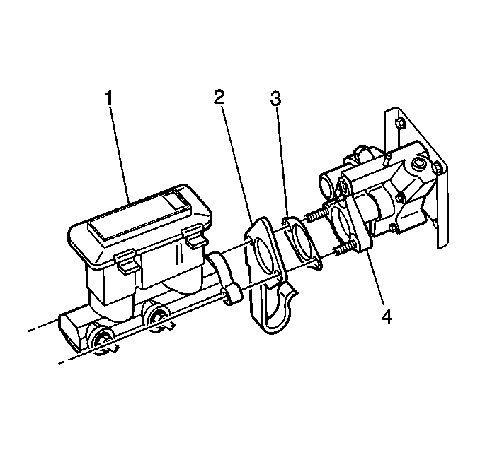
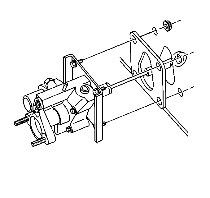
- Remove the wiring harness bracket (2).
- Remove the spacer (3) from the booster assembly (4).
- Remove the left closeout insulator panel. Refer to Instrument Panel Insulator Panel Replacement - Left Side .
- Remove the left knee bolster. Refer to Driver Knee Bolster Replacement .
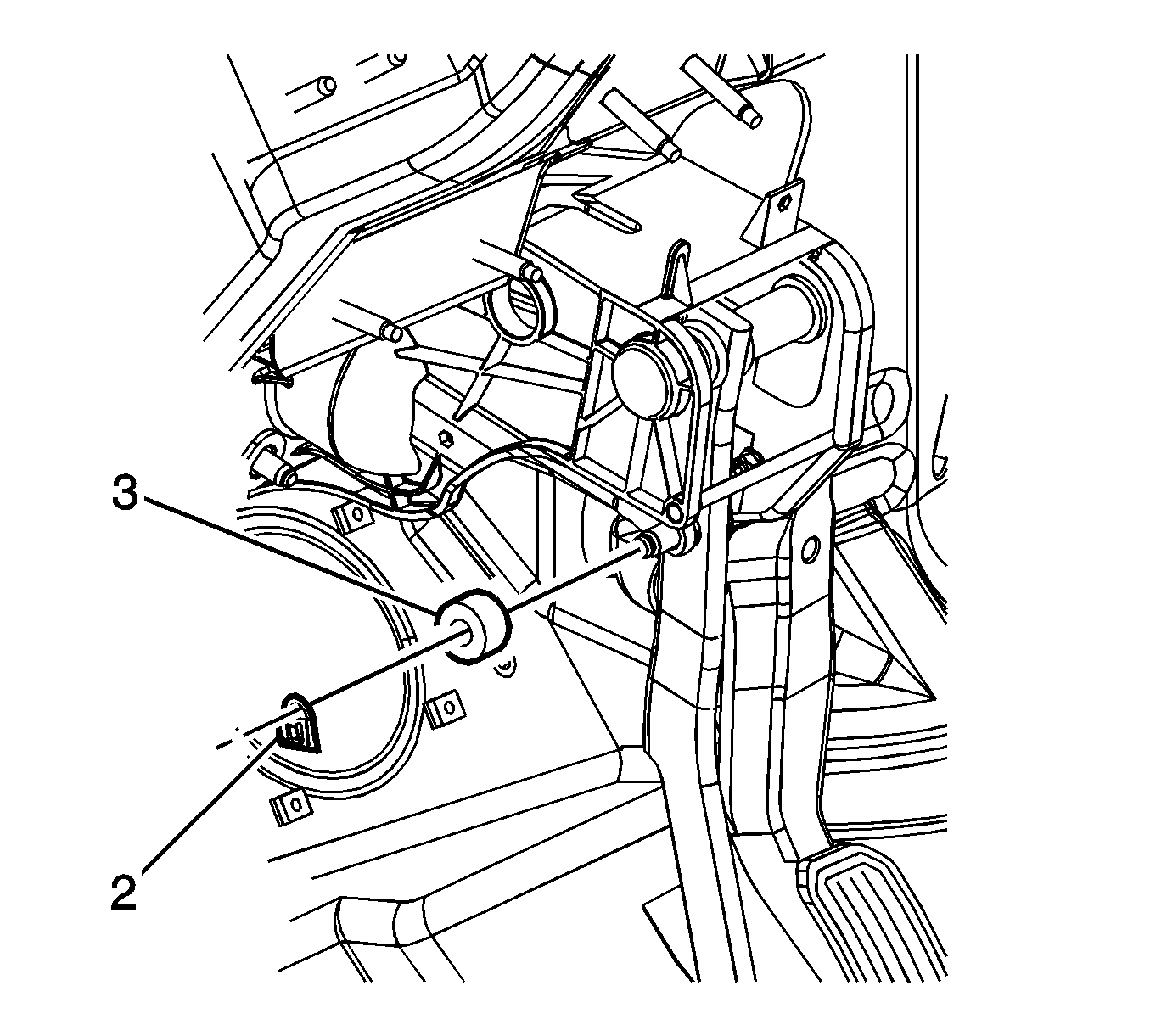
- Remove the vacuum brake booster retainer clip (2) from the brake pedal clevis pin.
- Remove the foam spacer (3) from the brake pedal clevis pin.
- Disconnect the vacuum brake booster push rod from the brake pedal clevis pin.
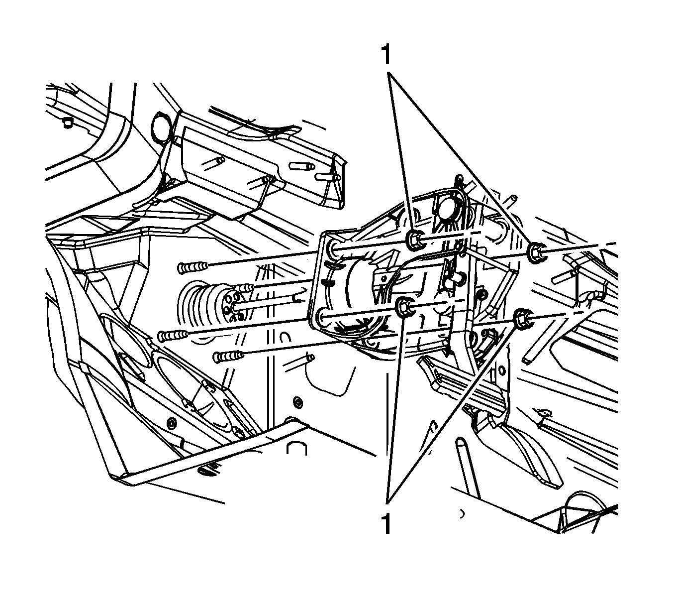
- Remove the vacuum brake booster mounting nuts (1) from the brake pedal assembly.
- Remove the vacuum brake booster assembly.
- Remove the vacuum brake booster mounting gasket, if gasket replacement is necessary.
Caution: Unless directed otherwise, the ignition and start switch must be in the OFF or LOCK position, and all electrical loads must be OFF before servicing any electrical component. Disconnect the negative battery cable to prevent an electrical spark should a tool or equipment come in contact with an exposed electrical terminal. Failure to follow these precautions may result in personal injury and/or damage to the vehicle or its components.
Installation Procedure
- Install the vacuum brake booster mounting gasket to the booster, if removed previously.
- Install the vacuum brake booster assembly to the vehicle.
- Install the brake pedal assembly to booster stud mounting nuts (1).
- Apply a small amount of lubricant, GM P/N 12346293 or equivalent to the clevis pin of the brake pedal.
- Connect the vacuum brake booster pushrod to the brake pedal assembly pedal clevis pin.
- Install the foam spacer (3) to the brake pedal assembly clevis pin.
- Install the retaining clip (2) to the brake pedal assembly clevis pin.
- Install the left knee bolster. Refer to Driver Knee Bolster Replacement .
- Install the left closeout insulator panel. Refer to Instrument Panel Insulator Panel Replacement - Left Side .
- Install the booster spacer (3).
- Install the wiring harness bracket (2).
- Install the master cylinder (1) to the booster assembly (4). Refer to Master Cylinder Replacement .
- Connect the power steering pressure hose. Refer to Power Steering Pressure Pipe/Hose Replacement .
- Connect the power steering gear to booster hose. Refer to Power Steering Pressure Pipe/Hose Replacement .
- Connect the power steering inlet hose. Refer to Power Steering Return Hose Replacement .
- Connect the negative battery cable.
- Bleed the hydraulic booster system. Refer to Power Steering System Bleeding .
- Recalibrate the brake position sensor. Refer to Brake Pedal Position Sensor Calibration .
- Remove the blocks from the front wheels.
- Release the park brake.
Notice: Use the correct fastener in the correct location. Replacement fasteners must be the correct part number for that application. Fasteners requiring replacement or fasteners requiring the use of thread locking compound or sealant are identified in the service procedure. Do not use paints, lubricants, or corrosion inhibitors on fasteners or fastener joint surfaces unless specified. These coatings affect fastener torque and joint clamping force and may damage the fastener. Use the correct tightening sequence and specifications when installing fasteners in order to avoid damage to parts and systems.
Tighten
Tighten the brake pedal assembly to booster stud mounting nuts to 36 N·m (27 lb ft).
